LC89057W-VF4A-E
_____
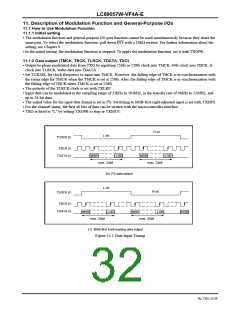
12. Microcontroller Interface (INT, CL, CE, DI, DO)
12.1 Description of Micr_o_c_o_ntroller Interface
12.1.1 Interrupt output (INT)
•
Interrupts are output when a change has occurred in the PLL lock status or output data information.
______
•
Interrupt output consists of the register for selecting the interrupt source, the INT pin that outputs that state transition,
and the registers that store the interrupt source data.
______
•
Normally INT outputs "L" upon occurrence of an interrupt while "H" is output. Following "L" output, it returns to "H"
according to the INTOPF setting.
•
INTOPF determines whether to hold the "L" pulse for a certain period and then clear it ("H"), or to clear it at a time
when the output register is read.
•
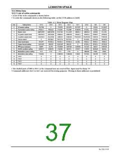
The interrupt sources can be selected among the following items. Multiple sources can be selected at the same time
______
with the contents of CCB address 0xE8 and command address 0x08. INT outputs OR calculation result of the selected
interrupt sources.
______
...
INT output = (selected source 1) + (selected source 2) + + (selected source n)
Table 12.1 Interrupt Source Setting Contents
No.
1
Command Name
ERROR
INDET
Description
Output when RERR pin status has changed
2
Output when input data pin status has changed (subject to oscillation amplifier operation condition)
Output when input fs calculation result has changed. (subject to oscillation amplifier condition)
3
FSCHG
CSRNW
UNPCM
PCRNW
SLIPO
4
Output when channel status data of first 48 bits have updated
______
5
Output when AUDIO pin status has changed
6
Output when burst preamble Pc has been updated
7
Output when data is read twice during slave setting and missing data is detected
Output when emphasis information has changed
8
EMPF
•
The contents of set interrupt source are saved in output registers DO8 to DO15 of CCB address 0xEA, when the
____________
source occurs. However, for the read registers for source items 1 and 5, the each status of the RERR and AUDIO pins
are output at the time of reading. Other data except for source items 1 and 5 are saved in the registers upon occurrence
of an interrupt source.
•
•
•
Concerning source items 2 and 3, the oscillation amplifier clock is used. Therefore, if the status is monitored even
while the PLL is locked, the oscillation amplifier must be set to the continuous operation mode.
______
Clearing INT at the same time of readout of an output register is carried out immediately after the output register
0xEA is set.
______
The pulse width of the setting in which the INT output following the occurrence of an interrupt source is set to the "L"
pulse output mode is somewhere between 1/2fs and 3/2fs for one interrupt source.
12.1.2 CCB format
•
The various function settings as well as information writing and reading are performed with the microcontroller
interface.
•
The data format of the microcontroller interface conforms to Sanyo's original serial bus format (CCB), but three-state
is employed instead of open-drain for the data output format.
•
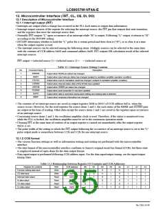
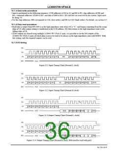
Data input/output is performed following CCB address input. For the data input/output timing, see the input/output
timing chart.
Table 12.2 Relationship between Register I/O Contents and CCB Addresses
Register I/O contents
Function setting data input
CS data input
R/W
Write
Write
Read
Read
Read
Read
CCB address
B0
B1
B2
B3
A0
A1
1
A2
1
A3
1
0xE8
0
0
0
1
0
0xE9
1
0
0
1
0
1
1
1
Interrupt data output
fs data output
0xEA
0
1
0
1
0
1
1
1
0xEB
1
1
0
1
0
1
1
1
CS data output
0xEC
0
0
1
1
0
1
1
1
Pc data output
0xED
1
0
1
1
0
1
1
1
No.7202-35/59

 SANYO [ SANYO SEMICON DEVICE ]