LC7218, 7218M, 7218JM
Continued from preceding page.
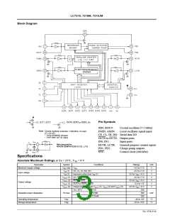
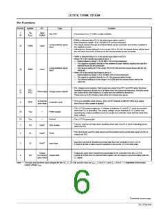
Pin No. Symbol
I/O
Type
Function
9
OUT0
OUT1
OUT2
OUT3
OUT4
OUT5
OUT6
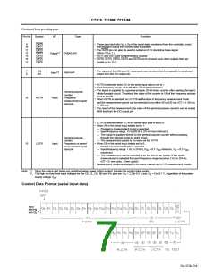
• These pins latch bits O to O in the serial data transferred from the controller, invert
0 6
10
11
12
13
14
17
that data and output the inverted data in parallel.
• The OUT0 pin can also be used to output an 8 Hz clock time base signal.
(When TB is 1.)
• OUT1 and OUT2 are complementary outputs.
• OUT0, OUT3, OUT4, OUT5 and OUT6 are N-channel open drain outputs that can
handle up to 13 V.
1
Output port
Output*
7
8
IN0
IN1
• The values of the IN0 and IN1 input ports can be converted from parallel to serial and
output from the DO output pin.
2
Input port
Input*
• HCTR is selected when SC in the serial input data is set to 1.
• Input frequency range: 10 to 60 MHz (70 mVrms minimum)
• The signal is supplied to a general-purpose 20-bit binary counter after passing through a
divide-by-eight circuit. Therefore, the value of the counter is 1/8 of the frequency actually
input to HCTR.
• When HCTR is selected the LC7218 will function in frequency measurement mode
and the measurement period can be selected to be either 60 or 120 ms. (GT = 0: 60 ms,
1: 120 ms)
General-purpose
counter
Frequency
measurement signal
input pin
16
HCTR
Input
• The result of the measurement (the value of the general-purpose counter) can be output
MSB first from the DO output pin.
• LCTR is selected when SC in the serial input data is set to 0.
• When SF in the serial input data is set to 1:
— Frequency measurement mode is selected.
— Input frequency range: 15 to 500 kHz (70 mVrms minimum).
— The signal is supplied directly to the general-purpose counter without passing
through the internal divide-by-eight circuit.
— The measurement period is the same as for HCTR.
• When SF in the serial input data is set to 0:
General-purpose
counter
Frequency or period
measurement signal
input pin
15
LCTR
Input
— Period measurement mode is selected.
— Input frequency range: 1 Hz to 20 kHz (V = 0.7 V
minimum, V = 0.3·V
IL DD
IH
DD
maximum)
— The measurement can be selected to be for one or two cycles. If two cycle
measurement is selected the input frequency range becomes 2 Hz to 20 kHz.
(GT = 0: one cycle, 1: two cycles)
• Measurement results are output in the same manner as HCTR measurement results.
Note: *1. Since the output port states are undefined when power is first applied, transfer the control data quickly.
*2. The high and low level input voltages for the CE, CL, DI, IN0 and IN1 pins are V = 2.2 to 6.5 V and V = 0 to 0.7 V, regardless of the power
IH
IL
supply voltage V
.
DD
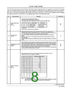
Control Data Format (serial input data)
No. 4758-7/16

 SANYO [ SANYO SEMICON DEVICE ]