LC7218, 7218M, 7218JM
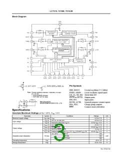
Block Diagram
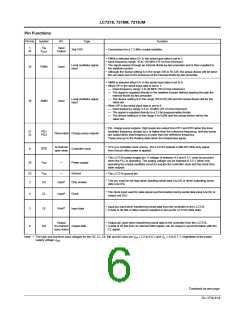
Pin Symbols
XIN, XOUT:
FMIN, AMIN:
Crystal oscillator (7.2 MHz)
Local oscillator signal input
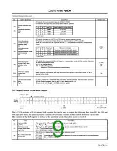
CE, CL, DI, DO: Serial data I/O
OUT0 to OUT6: Output ports
IN0, IN1:
HCTR, LCTR:
PD1, PD2:
SYC:
Input ports
General-purpose counter inputs
Charge pump outputs
Control clock (400 kHz)
Specifications
Absolute Maximum Ratings at Ta = 25°C, V = 0 V
SS
Parameter
Maximum supply voltage
Symbol
Conditions
Ratings
Unit
V
V
max
(1)
V
–0.3 to +7.0
–0.3 to +7.0
DD
DD
V
CE, CL, DI, IN0, IN1
Input pins other than V (1)
V
IN
Input voltage
V
(2)
–0.3 to V + 0.3
DD
V
IN
IN
V
(1) DO, SYC
–0.3 to +7.0
–0.3 to V + 0.3
V
OUT
OUT
OUT
OUT
V
V
V
(2) OUT1, OUT2
V
DD
Output voltage
(3) OUT3 to OUT6, OUT0
(4) Output pins other than V
–0.3 to +15
V
(1), V
(2) and V
(3)
–0.3 to V
DD
+ 0.3
350
300
200
V
OUT
OUT
OUT
Ta ≤ 85°C
:LC7218
Allowable power dissipation
Pd max
:LC7218M
mW
:LC7218JM
Operating temperature
Storage temperature
Topr
Tstg
–40 to +85
°C
°C
–55 to +125
No. 4758-3/16

 SANYO [ SANYO SEMICON DEVICE ]