LC7218, 7218M, 7218JM
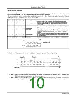
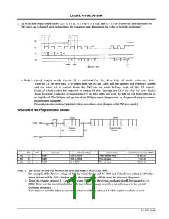
2. In serial data output mode (mode 3), t ≥ 1.5 µs, t ≥ 0 µs, t ≥ 1.5 µs, and t < 1.5 µs. (However, note that since the
1
2
3
5
DO pin is an n-channel open drain output, the transition time depends on the value of the pull-up resistor.)
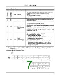
• Mode 3: Serial output mode (mode 3) is selected by the four bits of mode selection data.
When the CE pin goes high, I is output from the DO pin. After that, the internal shift register is shifted
O
and the next bit is output from the DO pin on each falling edge of the CL signal.
(Thus 27 clock cycles are required to output all data through the UL0 bit after CE goes high.)
When this mode is selected, at the point the CE pin falls to the low level, the DO pin will be forcibly set to
the high level. The DO pin will go low if the IN0 pin input changes state or if a general-purpose counter
measurement completes.
(General-purpose counter completion takes precedence over changes in the IN0 pin signal.)
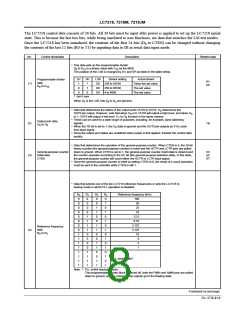
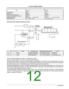
Structure of the Programmable Divider
DV
1
SP
*
Input pin
Divisor setting
256 to 65536
Actual divisor
Twice the set value
The set value
Input frequency range (MHz)
(A)
(B)
(C)
FMIN
AMIN
AMIN
10 to 130
2 to 40
0
1
256 to 65536
4 to 4096
0
0
The set value
0.5 to 10
Note: 1. The actual divisor will be twice the set value when FMIN (A) is used.
For example, if the divisor setting is 1000 the actual divisor will be 2000 and if the divisor setting is 1001 the
actual divisor will be 2002. In other words, the channel skip will be twice the reference frequency.
2. To set the channel skips of 1, 5 and 9 kHz using FMIN (A), the crystal oscillator should be changed to 3.6
MHz. However, the times listed in the table that follows change since they are referenced to the crystal
oscillator frequency.
Note that care must be taken to prevent overtone oscillation when a 3.6 MHz crystal oscillator is used.
No. 4758-11/16

 SANYO [ SANYO SEMICON DEVICE ]