LC7218, 7218M, 7218JM
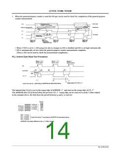
Serial Data I/O Methods
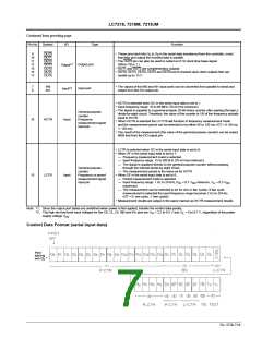
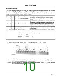
The LC7218 supports a total of three I/O modes: two control data input (serial data input) modes and one DO output
(serial data output) mode. Data I/O is performed after the mode has been determined.
The mode is selected by four data items (A to A ) synchronized with a clock (the CL pin) applied before the CE pin is
0
3
set high. The mode is determined when the CE pin goes high.
Mode
A
A
A
A
0
Item
Function
3
2
1
• This mode is used to input all 36 bits of the control data (serial input data).
This mode is used for initialization following power on and to change data that
cannot be changed in mode 2. All 36 bits of the control data is input from the
LC7218 DI pin.
1
0
0
0
1
Serial data input (all bits)
• This mode is used to input a subset (24 bits) of the control data (serial input
data).
This mode is used to change three data items: the programmable divider data
(D to D ), the output port data (O to O ) and the general-purpose counter
start data (CTEN), for a total of 24 bits. The other 12 bits of control data are not
changed by a mode 2 operation. (Use mode 1 when the other 12 bits must be
changed.)
Serial data input
(partial input)
2
3
0
0
0
0
1
1
0
1
0
15
0
6
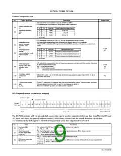
• The DO output mode (serial data output) is used to output three data items from
the DO pin: the input port data, the general-purpose counter binary data and the
PLL unlock state data.
Serial data output
0 to 0 1 to 0 0 to 0 0 to 0 Invalid setting
• This mode is invalid and does not support any data input or output operations.
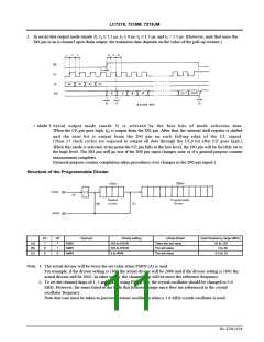
1. In the serial data input modes (modes 1 and 2), t ≥ 1.5 µs, t ≥ 0 µs, t ≥ 1.5 µs, and t < 1.5 µs.
1
2
3
4
• Mode 1: A total of 40 bits, the four mode selection bits and the 36 control data bits (from D to T ), are input from
0
1
the DI pin in synchronization with the clock (CL) signal.
• Mode 2: A total of 28 bits, the four mode selection bits and 24 control data bits (from D to CTEN), are input from
0
the DI pin in synchronization with the clock (CL) signal.
No. 4758-10/16

 SANYO [ SANYO SEMICON DEVICE ]