LA76810A
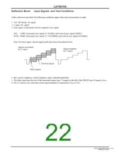
Deflection Block
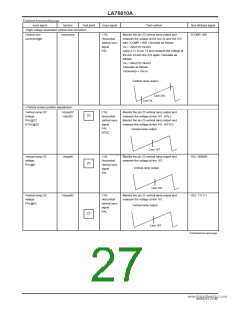
Test Conditions
Input signal
Symbol
Test point
Input signal
Test method
Bus bit/input signal
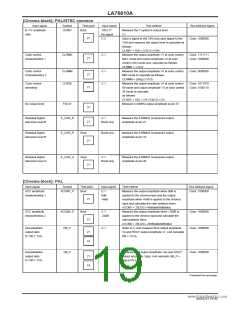
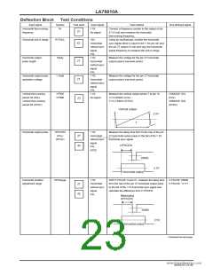
Horizontal free-running
frequency
fH
Y IN:
No signal
Connect a frequency counter to the output of pin
27 (H out) and measure the horizontal
27
free-running frequency.
Horizontal pull-in range
fH PULL
YIN:
Using an oscilloscope, monitor the horizontal
sync signal which is input to the Y IN (pin 42) and
the pin 27 output (H out) and vary the horizontal
signal frequency to measure the pull-in range.
42
27
27
Horizontal/
vertical sync
signal
PAL
Y IN:
Horizontal/
vertical sync
signal
PAL
Y IN:
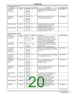
Horizontal output
pulse length
Hduty
Measure the voltage for the pin 27 horizontal
output pulse’s low-level period.
Horizontal output pulse
saturation voltage
V Hsat
Measure the voltage for the pin 27 horizontal
output pulse’s low-level period.
Horizontal/
vertical sync
signal
PAL
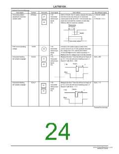
Vertical free-running
period 50 (PAL)
Vertical free-running
period 60 (NTSC)
VFR50
VFR60
Y IN:
No signal
Measure the vertical output period T at pin 18
T×15.625kHz (PAL)
T×15.734kHz (NTSC)
CDMODE: 001
(PAL)
CDMODE: 002
(NTSC)
23
Vertical output
2.5V
T
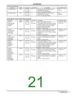
Horizontal output pulse
HPHCEN
(PAL)
(NTSC)
Y IN:
Horizontal/
vertical sync
signal
PAL
Measure the delay time from to the rise of the pin
27 horizontal output pulse to the fall of the Y IN
horizontal sync signal.
27
42
www.DataSheet4U.com
HPHCEN
NTSC
20IRE
2.5V
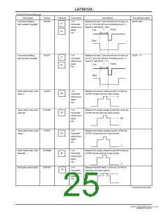
Horizontal output
Horizontal position
adjustment range
HPHrange
Y IN:
With H PHASE: 0 and 31, measure the delay time
from the rise of the pin 27 horizontal output pulse
to the fall of the Y IN horizontal sync signal and
calculate the difference from H PHCEN.
H PHASE: 00000
H PHASE: 11111
Horizontal/
vertical sync
signal
27
42
PAL
Measuring
HPHCEN
20IRE
2.5V
Horizontal output
Continued on next page.
NoA0252-23/40

 SANYO [ SANYO SEMICON DEVICE ]