LA76810A
Continued from preceding page.
Input signal
Symbol
GR_P
Test point
20
Input signal
Test method
Bus bit/input signal
Color: 1000000
Demodulation
output ratio
G-Y/R-Y: PAL
C-5
Measure Rout output amplitude Vrp and GOUT
output amplitude Vgbp. And calculate GR_P =
Vgrp/Vrp.
19
Demodulation
angle B-Y/R-Y:
PAL
ANGBR_P
C-1
Refer to 5. and measure the B-Y and R-Y
demodulation angle and calculate.
Color: 1000000
21
19
APC pull-in range (+)
APC pull-in range (-)
PULIN+_P
PULIN-_P
C-1
C-1
Decrease the chroma fsc frequency from
4.433619MHz+1000Hz and measure the
frequency at which the VCO locks.
Increase the chroma fsc frequency from
4.433619MHz-1000Hz and measure the
frequency at which the VCO locks.
21
21
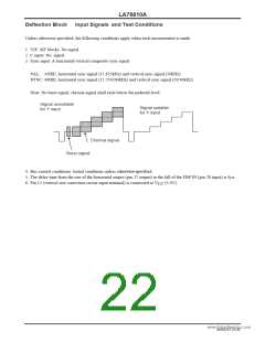
[Chroma block]: NTSC
Input signal
Symbol
Test point
Bout
Input signal
Test method
Bus bit/input signal
ACC amplitude
characteristics 1
ACCM1_N
C-1
0dB
+6dB
Measure the output amplitude when 0dB is
applied to the chroma input and the output
amplitude when +6dB is applied to the chroma
input and calculate the ratio between them.
ACCM1 = 20LOG (+6dBdata/0dBdata)
Measure the output amplitude when 20dB is
applied to the chroma input and calculate the
ratio between them.
21
ACC amplitude
characteristics 2
ACCM2_N
RB_N
Bout
21
C-1
-20dB
ACCM2 = 20LOG (-20dBdata/0dBdata)
www.DataSheet4U.com
R-Y/B-Y: NTSC
Demodulation
output ratio
C-1
Refer to 5. and measure Bout output amplitude
Vb and ROUT output amplitude Vr. And calculate
RB = Vr/Vb.
Color: 1000000
21
19
R-Y/B-Y: NTSC
G-Y/B-Y: NTSC
Demodulation
output ratio
R-Y/B-Y: NTSC
Demodulation
angle B-Y/R-Y:
NTSC
GB_N
C-1
C-1
Refer to 5. and measure GOUT output amplitude
Vg. And calculate GB_N = Vg/Vb.
Color: 1000000
Color: 1000000
20
ANGBR_N
Refer to 5. and measure the B-Y and R-Y
demodulation angle and calculate.
Reference: B-Y angle
21
19
Demodulation
angle G-Y/B-Y:
NTSC
ANGGB_N
C-1
Refer to 5. and measure the B-Y and G-Y
demodulation angle and calculate.
Reference: B-Y angle
Color: 1000000
21
20
Killer operating
point
KILL_N
PULIN+_N
PULIN-_N
TINCEN
C-1
C-1
C-1
C-1
Reduce the input signal until the output level
becomes 150mVp-p or less. Measure
the input level at that moment.
21
21
21
21
APC pull-in range (+)
APC pull-in range (-)
Tint center
Decrease the chroma fsc frequency from
3.579545MHz+1000Hz and measure the
frequency at which the VCO locks.
Increase the chroma fsc frequency from
3.579545MHz-1000Hz and measure the
frequency at which the VCO locks.
Measure each part of the output level and
calculate the B-Y axis angle.
TINT: 1000000
Continued on next page.
NoA0252-20/40

 SANYO [ SANYO SEMICON DEVICE ]