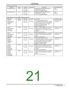
LA76810A
Continued from preceding page.
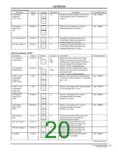
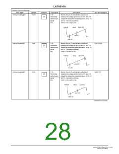
Input signal
Symbol
Test point
27
Input signal
Test method
Bus bit/input signal
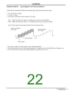
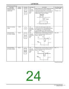
Horizontal position
adjustment maximum
variable width
HPHstep
Y IN:
With H PHASE: 0 to 31 varied, measure the delay
time from to the rise of the pin 27 horizontal
output pulse to the fall of the Y IN horizontal sync
signal and calculate the variation at each step.
Retrieve data for maximum variation.
H PHASE: 00000
to
H PHASE: 11111
Horizontal/
vertical sync
signal
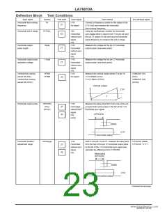
42
PAL
Measuring
HPHCEN
20IRE
Horizontal output
POR circuit operating
voltage
VPOR
BLKL0
Y IN:
Connect a DC power supply in place of the
current source to pin 25 and gradually decrease
the voltage from 5.0V until the BUS READ
TATUS [POR][STATUS1 (DA01) becomes "1".
Measure the DC voltage at pin 25 at the moment.
Measure the time T from the left end of Hsync at
pin 42 Y IN to the left end of blanking at pin 21
BlueOUT with BLKL = 000.
Horizontal/
vertical sync
signal
PAL
Y IN:
Horizontal/
vertical sync
signal
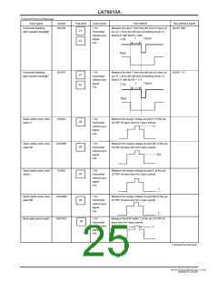
25
Horizontal blanking
left variable range@0
BLKL: 000
21
42
Hsync
Y IN
T
PAL
Blue
www.DataSheet4U.com
Horizontal blanking
left variable range@7
BLKL7
Y IN:
Measure the time T from the left end of Hsync at
pin 42 Y IN to the left end of blanking at pin 21
BlueOUT with BLKL = 111.
BLKL: 111
Horizontal/
vertical sync
signal
21
42
Hsync
Y IN
T
PAL
Blue
Continued on next page.
NoA0252-24/40

 SANYO [ SANYO SEMICON DEVICE ]