LA76810A
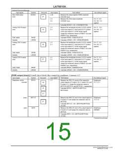
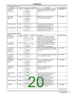
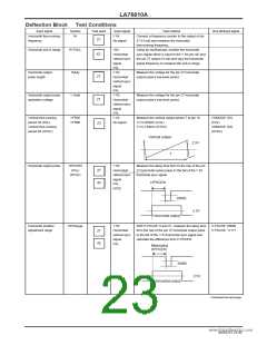
[Chroma block]: PAL/NTSC common
Input signal
Symbol
CLRBY
Test point
Bout
Input signal
Test method
Bus bit/input signal
Color: 1000000
B-Y/Y amplitude
ratio
YIN:L77
No signal
C-2
Measure the Y system’s output level.
V1
Input a signal to the CIN (only sync signal to the
YIN) and measure the output level to calculate as
follows:
21
CLRBY = 100 × (V2/V1)+15%
Color control
characteristics 1
CLRMN
C-1
Measure the output amplitude V1 at color control
MAX mode and output amplitude V2 at color
control CEN mode and, calculate as follows:
CLRMN = V1/V2
Color: 1111111
Color: 1000000
21
Color control
Characteristics 2
CLRMM
CLRSE
C-1
C-1
Measure the output amplitude V3 at color control
MIN mode to calculate as follows:
CLRMM = 20log (V1/V3)
Measure the output amplitude V4 at color control
90 mode and output amplitude V5 at color control
38 mode to calculate
Color: 0000000
21
21
Color control
sensitivity
Color: 1011010
Color: 0100110
as follows:
CLRSE = 100 × (V4-V5)/(V2×52)
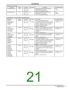
Measure 4.43MHz output amplitude at pin 37.
fsc output level
FSC37
37
21
Residual higher
harmonic level B
E_CAR_B
C-1
Burst only
Measure the 8.86MHz component output
amplitude at pin 21.
Residual higher
harmonic level R
E_CAR_R
E_CAR_G
Rout
Gout
Burst only
Measure the 8.86MHz component output
amplitude at pin 19.
21
21
www.DataSheet4U.com
Residual higher
harmonic level G
C-1
Burst only
Measure the 8.86MHz component output
amplitude at pin 20.
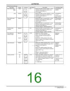
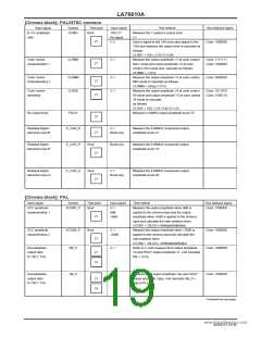
[Chroma block]: PAL
Input signal
Symbol
Test point
Bout
Input signal
Test method
Bus bit/input signal
Color: 1000000
ACC amplitude
characteristics 1
ACCM1_P
C-1
0dB
+6dB
Measure the output amplitude when 0dB is
applied to the chroma input and the output
amplitude when +6dB is applied to the chroma
input and calculate the ratio between them.
ACCM1 = 20LOG (+6dBdata/0dBdata)
Measure the output amplitude when –20dB is
applied to the chroma input and calculate the
ratio between them.
ACCM2 = 20LOG (-20dBdata/0dBdata)
Refer to 5. and measure Bout output amplitude
Vb and ROUT output amplitude Vr. And calculate
RB = Vr/Vb.
21
ACC amplitude
characteristics 2
ACCM2_P
RB_P
Bout
21
C-1
-20dB
Color: 1000000
Color: 1000000
Demodulation
output ratio
R-Y/B-Y: PAL
C-1
C-4
21
19
Demodulation
output ratio
G-Y/B-Y: PAL
GB_P
Measure Bout output amplitude Vbp and GOUT
output amplitude Vgbp. And calculate GB_P =
Vgb-p/Vb-p.
Color: 1000000
21
19
Continued on next page.
NoA0252-19/40

 SANYO [ SANYO SEMICON DEVICE ]