LA76810A
Continued from preceding page.
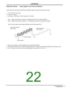
Input signal
Symbol
BGPPH
Test point
28
Input signal
Test method
Bus bit/input signal
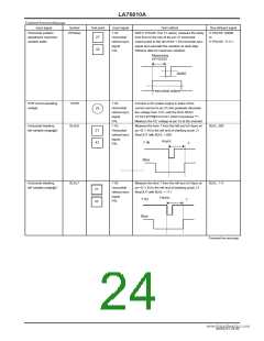
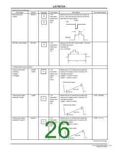
Burst gate pulse
I phase
Y IN:
Measure the time from the left end of Hsync at
pin 42 Y IN to the left end of the pin 28 FBP IN
wave form for Hsync period.
Horizontal/
vertical sync
signal
Hsync
Y IN
42
PAL
T
FB PIN
SECAM V pulse length
SECAMV
Y IN:
Measure the SECAM V pulse length T of the pin
28 FBPIN wave form.
Calculate as:
28
Horizontal/v
ertical sync
signal
T(s) ×15.625kHz
PAL
T
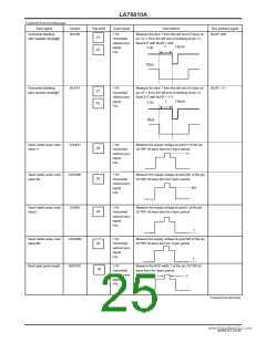
<Vertical screen size correction>
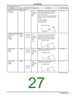
Vertical ramp output
Amplitude
PAL@64
Vspal64
Vsnt64
Y IN:
Horizontal/
vertical sync
Monitor the pin 23 vertical ramp output and
measure the voltage at line 24 and line 310.
Calculate as follows:
23
NTSC@64
signalwww.DataSheeVt4sUp.caolm64 = Vline310-Vline24
PAL
Vsnt64 = Vline262-Vline22
NTSC
Vertical ramp output
Line 310
Line 24
Vertical ramp output
amplitude PAL@0
Vspal0
Y IN:
Monitor the pin 23 vertical ramp output and
measure the voltage at line 24 and line 310
Calculate as follows:
VSIZE: 0000000
Horizontal/
vertical sync
signal
23
Vspal0 = Vline310-Vline24
PAL
Vertical ramp output
Line 310
Line 24
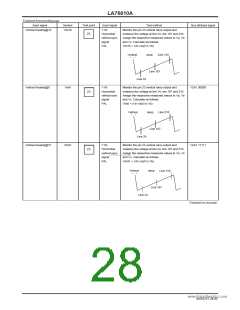
Vertical ramp output
amplitude PAL@127
Vspal127
Y IN:
Monitor the pin 23 vertical ramp output and
measure the voltage at line 24 and line 310
Calculate as follows:
VSIZE: 1111111
Horizontal/
vertical sync
signal
23
Vspal27 = Vline310-Vline24
PAL
Vertical ramp output
Line 310
Line 24
Continued on next page.
NoA0252-26/40

 SANYO [ SANYO SEMICON DEVICE ]