LA76810A
Continued from preceding page.
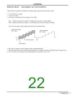
Input signal
Symbol
BLKR0
Test point
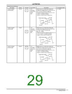
21
Input signal
Test method
Bus bit/input signal
BLKR: 000
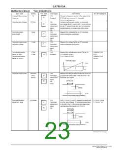
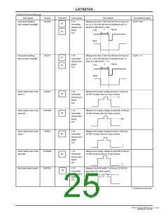
Horizontal blanking
right variable range@0
Y IN:
Measure the time T from the left end of Hsync at
pin 42 Y IN to the left end of blanking at pin 21
BlueOUT with BLKR = 000.
Horizontal/
vertical sync
signal
Hsync
T
Y IN
42
PAL
Blue
Horizontal blanking
right variable range@7
BLKR7
Y IN:
Measure the time T from the left end of Hsync at
pin 42 Y IN to the left end of blanking at pin 21
BlueOUT with BLKR = 111.
BLKR: 111
21
42
Horizontal/
vertical sync
signal
Hsync
T
Y IN
PAL
Blue
Sand castle pulse crest
value H
SANDH
Y IN:
Measure the supply voltage at point H of the pin
28 FBP IN wave form for Hsync period.
H
28
28
Horizontal/
vertical sync
signal
PAL
www.DataSheet4U.com
Sand castle pulse crest
value M1
SANDM1
Y IN:
Measure the supply voltage at point M1 of the pin
28 FBP IN wave form for Hsync period.
Horizontal/
vertical sync
signal
M1
PAL
Sand castle pulse crest
value L
SANDL
Y IN:
Measure the supply voltage at point L of the pin
28 FBP IN wave form for Hsync period.
28
Horizontal/
vertical sync
signal
PAL
L
Sand castle pulse crest
value M2
SANDM2
BGPWD
Y IN:
Measure the supply voltage at point M2 of the pin
28 FBP IN wave form for Vsync period.
Horizontal/
vertical sync
signal
28
28
PAL
L
Burst gate pulse length
Y IN:
Measure the BGP width T of the pin 28 FBP IN
wave form for Hsync period.
Horizontal/
vertical sync
signal
T
PAL
Continued on next page.
NoA0252-25/40

 SANYO [ SANYO SEMICON DEVICE ]