S3C4510B
DMA CONTROLLER
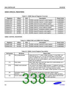
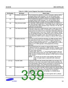
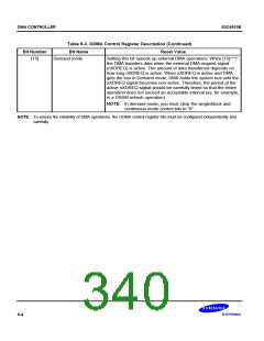
Table 9-3. GDMA Control Register Description (Continued)
Bit Number
Bit Name
Reset Value
Destination address fix
This bit determines whether or not the destination address will be
changed during a DMA operation. You use this feature when
transferring data from multiple sources to a single destination.
[6]
[7]
[8]
Source address fix
This bit determines whether or not the source address will be
changed during a DMA operation. You use this feature when
transferring data from a single source to multiple destinations.
Stop interrupt enable
To start/stop a DMA operation, you set/clear the run enable bit. If
the stop interrupt enable bit is "1" when DMA starts, a stop interrupt
is generated when DMA operation stops. If this bit is "0", the stop
interrupt is not generated.
Four-data burst enable
If this bit is set to one, GDMA operates under 4-data burst mode.
under the 4-data burst mode, 4 consecutive source addresses are
read and then are written to the consecutive destination addresses.
If 4-data burst mode is set to one, "transfer count register" should
be set carefully because the 4-data burst move is executed during
decreasing of the transfer count. The 4-data burst mode can be
used only when GMDA mode is software or external DMA request
mode.
[9]
Peripheral direction
Single/Block mode
This bit is used to specify the direction of a DMA operation when
the mode bits [3:2] are set to '10' (UART0 from/to memory) or '11'
(UART1 from/to memory). If this bit is "1", DMA operates in the
memory-to-peripheral direction (e.g., to the parallel port or UART).
When it is "0", DMA operates in the peripheral-to-memory
direction.
[10]
[11]
This bit determines the number of external DMA requests
(nXDREQs) that are required for a DMA operation. In Single mode,
when [11] = "0", the S3C4510B requires an external DMA request
for every DMA operation.
In Block mode, when [11] = "1", the S3C4510B requires only one
external DMA request during the entire DMA operation. An entire
DMA operation is defined as the operation of DMA until the counter
value is zero.
NOTE: You should not use block mode together with demand
mode, or single mode in conjunction with continuous
mode.
Transfer width
These bits determine the transfer data width to be one byte, one
half-word, or one word. If you select a byte transfer operation, the
source/destination address will be incremented or decremented by
one with each transfer. Each half-word transfer increments or
decrements the address by two, and each word transfer by four.
[13:12]
[14]
Continuous mode
This bit lets the DMA controller hold the system bus until the DMA
transfer count value is zero. You must therefore manipulate this bit
carefully so that DMA transfer operations do not exceed a
acceptable time interval (as, for example, in a DRAM refresh
operation).
NOTE: You can use continuous mode together with a software
request mode.
9-3

 SAMSUNG [ SAMSUNG ]