S3C4510B
ETHERNET CONTROLLER
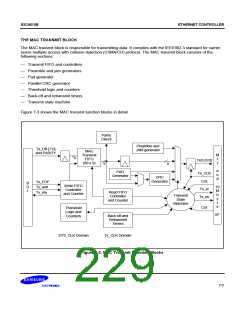
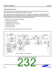
Receive FIFO Controller
The receive FIFO controller accepts data one byte at a time. Parity starts with the destination address. The
receive controller updates the counter with the number of bytes received. As the FIFO stores the data, the CAM
block checks the destination address against its stored address. If the CAM recognizes the address, the FIFO
continues receiving the packet. If the CAM block does not recognize the address and rejects the packet, the
receive block discards the packet and flushes the FIFO.
Address CAM and Address Recognition
The CAM block provides direct comparison address recognition. The CAM compares the destination address of
the received packet to stored addresses. If it finds a match, the receive state machine continues to receive the
packet. The CAM is organized to hold six-byte address entries. With its 32-word size, the CAM can store 21
address entries.
CAM address entries 0, 1, and 18 are used to send the pause control packet. To send a pause control packet,
you must write the destination address to CAM0, the source address to CAM1, and length/type, op-code, and
operand to the CAM18 entry. You must them write the MAC transmit control register to set the send pause
control bit. In addition, CAM19 and CAM20 can be used to construct a user-define control frame.
Parallel CRC Checker
The receive block computes a CRC across the data and the transmitted CRC, and then checks that the resulting
syndrome is valid. A parallel CRC checking scheme handles data arriving in 4-bit nibbles at 100 Mbps. To
support full-duplex operation, the receive and transmit blocks have independent CRC circuits.
Receive State Machine
In MII mode, the receive block receives data from the MII on the RxD[3:0] lines. This data is synchronized to
Rx_clk at 25 MHz or 2.5 MHz. In 7-wire mode, and at 10 MHz, data is received on the RxD_10 line only.
After it detects the preamble and SFD, the receive state machine arranges data in byte configurations, generates
parity, and stores the result in the receive FIFO one byte at a time. If the CAM block accepts the destination
address, the receive FIFO stores the rest of the packet. At the end of the reception, the receive block marks the
packet received by setting the appropriate bits in the receive status register. Any error in reception will reset the
FIFO and the state machine will wait for the end of the current packet. It will then idle while it is waiting for the
next preamble and SFD.
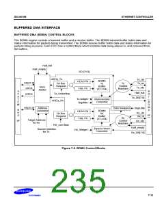
BDMA Interface Receive State Machine
The BDMA I/F receive state machine issues the Rx_rdy signal to request that the receive FIFO have data
whenever data is present in the receive FIFO. The last byte of the packet is signaled by asserting the Rx_EOF.
In case there are any errors during the reception, or if there is a CRC error at the end, the BDMA I/F receive
state machine asserts the Rx_toss signal to indicate that the received packet should be discarded.
7-11

 SAMSUNG [ SAMSUNG ]