S3C4510B
ETHERNET CONTROLLER
BDMA Bus Control Logic
The function blocks of the BDMA controller provide logic for controlling bus master read and write operations
across the system bus. This control logic supports the following operations:
— Burst size control, to optimize system bus utilization.
— Transmit threshold control (based on 1/8 of transmit buffer size) to match transmission latency to system bus
latency.
— Little-Endian byte swapping, to support the data transfer of Little-Endian memory usage for frame data.
— A transmit/receive alignment widget to circumvent word alignment restrictions.
In systems with an ATM LAN emulation or an MPOA interface, and in certain other systems as well, the
beginning of a packet should be placed on a byte or half-word boundary. You may not, however misalign the
BDMA transfer, as this would complicate the design of the DMA, and would degrade performance. To avoid this,
you can use an alignment widget between the BDMA buffer (word) and the MAC FIFO (byte).
In the receiver, the BDMA bus control logic inserts a programmable number of bytes (up to three) into the
received data stream while the preamble is being received. This adds some padding to the beginning of the
frame. This padding can then be used to solve alignment problems downstream, without having to use a copy of
the buffer. Because there is never more than three bytes, this feature does not degrade performance. Also,
because the data is inserted prior to the concatenation of bytes into words, it does not misalign the subsequent
DMA transfer.
The length of the alignment data is read from a control register. This length value should be set by software
immediately after the MAC module is reset, and it should not be modified.
You can use a corresponding transmit alignment widget to remove data from the buffer. In the simplest
implementation, the widget discards the first "n" bytes (up to three), where "n" is the value read from the transmit
frame descriptor which configures the transmit alignment widget.
MEMORY DATA STRUCTURES
The flow control 100-/10-Mbit/s ethernet controller uses three data structures to exchange control information and
data:
— Transmit frame descriptor
— Receive frame descriptor
— Frame data buffer
Each frame descriptor has the following elements:
— Frame start address
— Ownership bit
— Control field for transmitter
— Status field
— Frame length
— Next frame descriptor pointer
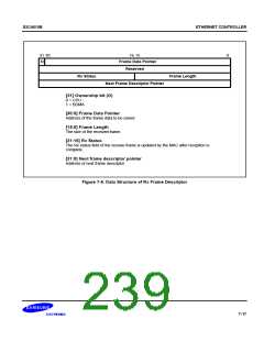
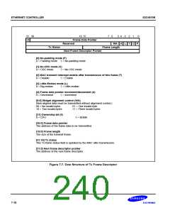
Figure 7-6 shows data structures of the transmit and receive frame descriptors.
7-15

 SAMSUNG [ SAMSUNG ]