64M DDR SDRAM
K4D623238B-GC
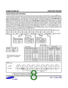
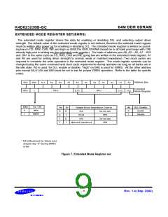
EXTENDED MODE REGISTER SET(EMRS)
The extended mode register stores the data for enabling or disabling DLL and selecting output driver
strength. The default value of the extended mode register is not defined, therefore the extened mode register
must be written after power up for enabling or disabling DLL. The extended mode register is written by assert-
ing low on CS, RAS, CAS, WE and high on BA0(The DDR SDRAM should be in all bank precharge with CKE
already high prior to writing into the extended mode register). The state of address pins A0, A2 ~ A5, A7 ~ A10
and BA1 in the same cycle as CS, RAS, CAS and WE going low are written in the extended mode register. A1
and A6 are used for setting driver strength to normal, weak or matched impedance. Two clock cycles are
required to complete the write operation in the extended mode register. The mode register contents can be
changed using the same command and clock cycle requirements during operation as long as all banks are in
the idle state. A0 is used for DLL enable or disable. "High" on BA0 is used for EMRS. All the other address
pins except A0,A1,A6 and BA0 must be set to low for proper EMRS operation. Refer to the table for specific
codes.
Address Bus
BA1
RFU
BA0
1
A10
A9
A8
A7
A6
A5
A4
A3
A2
A1
A0
Extended
Mode Register
RFU
D.I.C
RFU
D.I.C
DLL
BA0
An ~ A0
A0
0
DLL Enable
Enable
A6
0
A1
Output Driver Impedence Control
0
1
MRS
0
1
0
1
N/A
Weak
Do not use
60%
EMRS
1
Disable
0
1
N/A
Do not use
30%
1
Matched impedance
* RFU(Reserved for future use)
should stay "0" during EMRS
cycle.
Figure 7. Extended Mode Register set
- 9 -
Rev. 1.4 (Sep. 2002)

 SAMSUNG [ SAMSUNG ]