2X20 LCD Compatible VFD Module
20T202DA1E (Rev. 3.0)
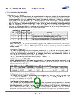
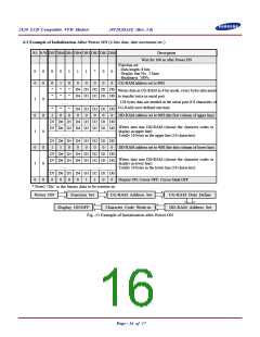
6.3 Example of Initialization After Power ON (4-bits data, date increment etc.)
RS R/W DB7 DB6 DB5 DB4 DB3 DB2 DB1 DB0
Description
Wait for 100 us after Power ON
Function set:
- Data length: 8 bits
- Display line No.: 2 lines
- Brightness: 100%
0
0
0
0
0
0
1
1
0
1
0
*
0
0
0
0
0
0
*
*
1
0
*
*
CG-RAM address set to 00H
*
D4 D3 D2 D1 D0
D4 D3 D2 D1 D0
……
Writes data in CG-RAM in 4-bit mode, every bytes data needs
to transfer twice in serial port.
*
1
0
1
0
1
0
0
0
0
0
0
0
128 bytes data are needed in the serial port if 8 characters of
CG-RAM were defined one time.
……
*
1
*
0
*
0
D4 D3 D2 D1 D0
0
0
0
0
0
DD-RAM address set to 00H (the first column of upper line)
D7 D6 D5 D4 D3 D2 D1 D0
D7 D6 D5 D4 D3 D2 D1 D0
Writes data into DD-RAM (choose the character codes to
display in upper line)
Totally 16 bytes in the upper line (16 characters)
……
……
D7 D6 D5 D4 D3 D2 D1 D0
1
1
0
0
0
0
0
0
DD-RAM address set to 40H (the first column of lower line)
D7 D6 D5 D4 D3 D2 D1 D0
D7 D6 D5 D4 D3 D2 D1 D0
Writes data into DD-RAM (choose the character codes to
display in lower line)
Totally 16 bytes in the lower line (16 characters)
……
……
D7 D6 D5 D4 D3 D2 D1 D0
0
0
0
0
1
1
0
0
Display ON, Cursor OFF, Cursor blink OFF
* Note) “Dn” is the binary data to be written-in.
Power ON
Function Set
CG-RAM Address Set
CG-RAM Data Define
DD-RAM Address Set
Display ON/OFF
Character Code Write-in
Fig.-13 Example of Initialization after Power ON
Page - 16 of 17

 SAMSUNG [ SAMSUNG ]