2X20 LCD Compatible VFD Module
20T202DA1E (Rev. 3.0)
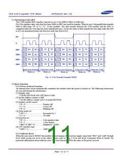
5.2 Interfacing to the MPU
This VFD module MPU interface operates in two 4-bit (DB4 to DB7) in M68 type.
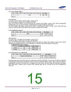
For 4-bit interface data, only four bus lines (DB4 to DB7) are used for transfer. When to use 4-bit parallel data transfer,
DB0 to DB3 keep "H" or "L" ("L" in this module). The data transfer between the VFD module and the MPU is
completed after the 4-bit data has been transferred twice. As for the order of data transfer the four high order bits (D4
to D7) are transferred before the four low order bits (D0 to D3).
RS
E
D3
D2
D1
D0
D3
D2
D1
D0
D7
D6
D5
D4
D7
D6
D5
D4
IR3
IR3
IR7
IR6
IR5
IR4
IR7
IR6
IR5
IR4
D3
D2
D7
D6
DB7
DB6
IR2
IR1
IR2
IR1
D1
D0
D5
D4
DB5
DB4
IR0
IR0
Instruction Register Character Code
Write-in Write-in
Character Code
Write-in
Instruction Register
Write-in
Character Code
Write-in
Fig.-11 4-bit Transfer Example (M68)
5.3 Reset Function
5.3.1 Power-on Reset Function
An internal reset circuit automatically initializes the module when the power is turned on. The following instructions
are executed during the initialization.
(1) Display clear
* Fill the DD-RAM with 20H (Space Code)
(2) Set the address counter to 00H
* Set the address counter (ACC) to point DD-RAM.
(3) Display on/off control:
* D = 0...................................Display off
* C = 0...................................Cursor off
* B = 0...................................Blinking off
(4) Entry mode set:
* I/D = 1................................ Increment by 1
* S = 0....................................No shift
(5) Function set
* IF = 0 .................................4-bit interface data
* N = 1 ..................................2-line display
* BR0 =0, BR1 =0.................Brightness = 100%
(6) CPU interface type
* MPU = 1..........................…M68 type
5.3.2 Software Reset
When the user want to RESET the module without turning off the power supply, input both "RST" and "Add" bit high
level while giving low level to the others. Please refer to "Fig.-3 CLK and Reset Command Write-in Detail" for
particular information about software reset. The reset function will be the same as the power-on reset.
Page - 11 of 17

 SAMSUNG [ SAMSUNG ]