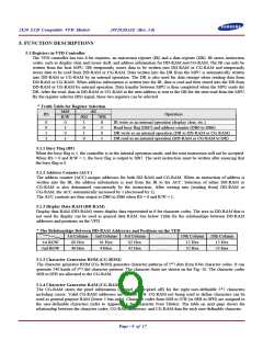
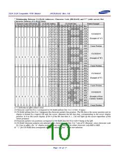
2X20 LCD Compatible VFD Module
20T202DA1E (Rev. 3.0)
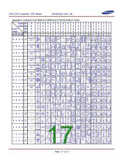
6.2 Instruction Descriptions
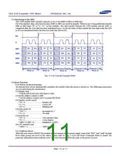
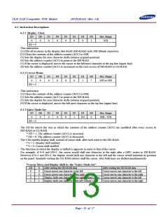
6.2.1 Display Clear
D7
0
D6
0
D5
0
D4
0
D3
0
D2
0
D1
0
D0
1
Hex. Range
01H
RS = 0
This instruction
(1) Fills all locations in the display data RAM (DD-RAM) with 20H (Blank-character).
(2) Clears the contents of the address counter (ACC) to 00H.
(3) Sets the display for zero character shifts (returns original position).
(4) Sets the address counter (ACC) to point to the DD-RAM.
(5) If the cursor is displayed, moves the cursor to the left most character in the top line (upper line).
(6) Sets the address counter (ACC) to increment on the each access of DD-RAM or CG-RAM.
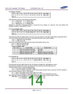
6.2.2 Cursor Home
D7
0
D6
0
D5
0
D4
0
D3
0
D2
0
D1
1
D0
*
Hex. Range
02H or 03H
RS = 0
This instruction
(1) Clears the contents of the address counter (ACC) to 00H.
(2) Sets the address counter (ACC) to point to the DD-RAM.
(3) Sets the display for zero character shifts (returns original position).
(4) If the cursor is displayed, moves the left most character in the top line (upper line).
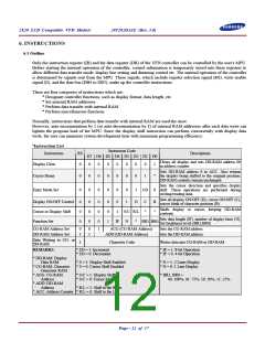
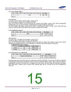
6.2.3 Entry Mode Set
D7
0
D6
0
D5
0
D4
0
D3
0
D2
1
D1
I/D
D0
S
Hex. Range
04H ~ 07H
RS = 0
The I/D bit selects the way in which the contents of the address counter (ACC) are modified after every access to
DD-RAM or CG-RAM.
* I/D = 1: The address counter (ACC) is increased.
* I/D = 0: The address counter (ACC) is decreased.
The S bit enables display shift, instead of cursor shift, after each write to the DD-RAM.
* S = 1: Display shift enabled.
* S = 0: Cursor shift enabled.
The direction in which the display is shifted is opposite in sense to that of the cursor.
For example, if S=0 and I/D=1, the cursor would shift one character to the right after a MPU writes to DD-RAM.
However if S=1 and I/D=1, the display would shift one character to the left and the cursor would maintain its position
on the panel. Similarly writing the CG-RAM always shift the cursor. Also both lines are shifted simultaneously.
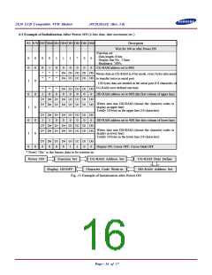
*Cursor Move and Display Shift by the "Entry Mode Set"
I/D
0
S
0
0
1
1
After writing the DD-RAM data
After reading the DD-RAM data
Cursor moves one character to the left
Cursor moves one character to the right
Cursor moves one character to the left
Cursor moves one character to the right
1
0
Display shifts one character to the right without cursor Cursor moves one character to the left
1
Display shifts one character to the left without cursor
Cursor moves one character to the right
Page - 13 of 17

 SAMSUNG [ SAMSUNG ]