2X20 LCD Compatible VFD Module
20T202DA1E (Rev. 3.0)
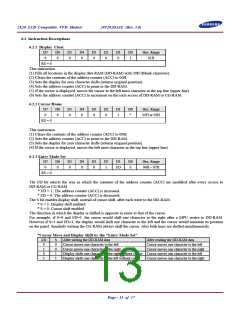
6.2.4 Display ON/OFF
D7
0
D6
0
D5
0
D4
0
D3
1
D2
D
D1
C
D0
B
Hex. Range
08H ~ 0FH
RS = 0
This instruction controls various features of the display.
* D = 1: Display ON, D = 0: Display OFF.
* C = 1: Cursor ON, C = 0: Cursor OFF.
* B = 1: Blinking ON, B = 0: Blinking OFF.
(Blinking is achieved by alternating between a normal and all on display of a character. The cursor blinks with
frequency of about 1.0 Hz and DUTY 50%.)
6.2.5 Cursor/Display Shift
D7
0
D6
0
D5
0
D4
1
D3
D2
D1
*
D0
*
Hex. Range
10H ~ 1FH
S/C
R/L
RS = 0
This instruction shifts the display and/or moves the cursor one character to the left or right without writing DD-RAM.
The S/C bit selects movement of the cursor or movement of both the cursor and the display.
* S/C = 1: Shift both cursor and display
* S/C = 0: Shift cursor only
The R/L bit selects left ward or right ward movement of the display and/or cursor.
* R/L = 1: Shift one character right
* R/L = 0: Shift one character left
*Cursor or Display Shift
S/C R/L
Cursor Shift
Display Shift
0
0
1
1
0
1
0
1
Move one character to the left
Move one character to the right
Shift one character to the left
Shift one character to the
No shift
No shift
Shift one character to the left
Shift one character to the right
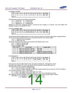
6.2.6 Function Set
D7
0
D6
0
D5
1
D4
IF
D3
N
D2
*
D1
D0
Hex. Range
20H ~ 3FH
BR1
BR0
RS = 0
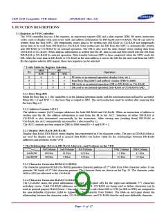
This instruction sets the width of data bus line, the number of display line, and brightness control.
This instruction initializes the system, and must be the first instruction executed after power-on.
The IF bit selects a 8-bit or 4-bit bus width interface.
* IF = 1: 8-bit CPU interface using DB7 to DB0
* IF = 0: 4-bit CPU interface using DB7 to DB4 (This module should be always chosen by 4-bit CPU interface).
The N bit selects between 1-line or 2-line display.
* N = 1: Select 2 line display (Using anode output A1 to A80)
* N = 0: Select 1 line display (Using anode output A1 to A40. A41 to A80 fixed Low level).
BR1, BR0 flag controls the brightness of VFD by modulating pulse width of Anode output as follows.
* BR0, BR1 = (0, 0): Brightness = 100%, (0, 1): Brightness = 75%,
(1, 0): Brightness = 50%, (1, 1): Brightness = 25%.
Page - 14 of 17

 SAMSUNG [ SAMSUNG ]