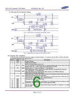
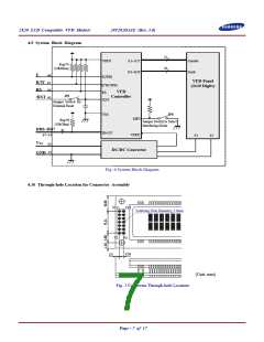
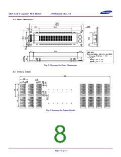
2X20 LCD Compatible VFD Module
20T202DA1E (Rev. 3.0)
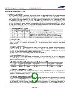
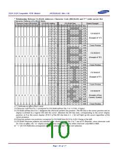
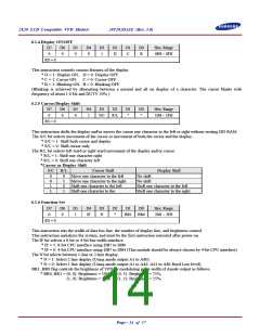
* Relationship Between CG-RAM Addresses, Character Code (DD-RAM) and 5*7 (with cursor) Dot
Character Patterns (CG-RAM data).
Character Codes (DD-RAM)
CG-RAM Address
CG-RAM Data
Pattern Example
D7 D6 D5 D4 D3 D2 D1 D0 A5 A4 A3 A2 A1 A0 D7 D6 D5 D4 D3 D2 D1 D0 Hex.
0
0
0
0
1
1
1
1
0
0
0
0
1
1
1
1
0
0
0
0
1
1
1
1
0
0
0
0
1
1
1
1
0
0
1
1
0
0
1
1
0
0
1
1
0
0
1
1
0
0
1
1
0
0
1
1
0
0
1
1
0
0
1
1
0
1
0
1
0
1
0
1
0
1
0
1
0
1
0
1
0
1
0
1
0
1
0
1
0
1
0
1
0
1
0
1
*
*
*
*
*
*
*
*
*
*
*
*
*
*
*
*
*
*
*
*
*
*
*
*
*
*
*
*
*
*
*
*
*
*
*
*
*
*
*
*
*
*
*
*
*
*
*
*
*
*
*
*
*
*
*
*
*
*
*
*
*
*
*
*
*
*
*
*
*
*
*
*
*
*
*
*
*
*
*
*
*
*
*
*
*
*
*
*
*
*
*
*
*
*
*
*
0
1
1
1
1
1
1
0
1
1
1
1
1
1
1
0
0
0
0
0
0
0
0
0
0
0
1
0
1
0
0
0
1
0
0
1
0
0
0
*
1
0
0
1
0
0
1
*
1
0
0
0
0
0
1
*
0
1
1
1
1
1
0
*
1
0
0
1
0
0
0
*
1
0
0
1
0
0
1
*
1
1
1
1
1
1
1
*
1
0
1
0
1
0
1
*
1
0
0
1
0
0
0
*
1
0
0
1
0
0
1
*
1
0
0
0
0
0
1
*
1
0
0
0
0
0
1
*
0
1
1
1
1
1
1
*
0
1
1
0
1
1
0
*
0
0
0
0
0
0
0
*
0
0
0
0
0
1
0
*
0EH
11H
11H
1FH
11H
11H
11H
00H
1EH
11H
11H
1EH
11H
11H
1EH
00H
0EH
04H
04H
04H
04H
04H
0EH
00H
06H
08H
1CH
08H
1CH
09H
06H
00H
CG-RAM #1
0
0
0
0
0
0
0
0
0
0
0
0
0
0
0
0
*
*
*
*
0
0
0
0
0
0
1
1
0
1
0
1
0
0
0
0
0
0
1
1
0
1
0
1
(Example of "A")
Cursor Position
CG-RAM #2
(Example of "B")
Cursor Position
CG-RAM #3
(Example of "I")
Cursor Position
CG-RAM #4
(Example of Euro
Currency Symbol)
Cursor Position
1) *: Indicates no effect (Don't care).
2) Character code bits 0 to 2 correspond to CG-RAM address bits 3 to 5 (3 bits: 8 types).
3) CG-RAM address bits 0 to 2 designate the character pattern line position. The 8th line is the cursor position and its
display is formed by a logical OR with the cursor. Maintain the 8th line data, corresponding to the cursor display
position, at 0 as the cursor display. If bit 4 of the 8th line data is 1, 1 bit will light up the cursor regardless of the
cursor presence.
4) Character pattern row positions correspond to CG-RAM data bits 0 to 4 (bit 4 being at the left).
5) CG-RAM character patterns are selected when character code bits 4 to 7 are all 0. However, since character code
bit 3 has no effect, the “A” display example above can be selected by either character code 00H or 08H.
6) ” 1” for CG-RAM data corresponds to display selection and ” 0” to non-selection.
Page - 10 of 17

 SAMSUNG [ SAMSUNG ]