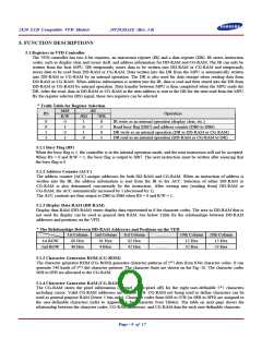
2X20 LCD Compatible VFD Module
20T202DA1E (Rev. 3.0)
6.2.7 Set CG-RAM Address
D7
0
D6
1
D5
D4
D3
D2
D1
D0
Hex. Range
40H ~ 7FH
ACG
RS = 0
This instruction:
(1) Load a new 6-bit address into the address counter (ACC).
(2) Sets the address counter (ACC) to address CG-RAM.
Once "Set CG-RAM Address" has been executed, the contents of the address counter (ACC) will be automatically
modified after every access of CG-RAM, as determined by the "Entry Mode Set" instruction".
The active width of the address counter (ACC), when it is addressing CG-RAM, is 6 bits, so the counter will wrap
around to 3FH from 00H if more than 64 bytes of data are written into CG-RAM.
6.2.8 Set DD-RAM Address
D7
1
D6
D5
D4
D3
D2
D1
D0
Hex. Range
ADD
80H ~ A7H for 1st Line
C0H ~ E7H for 2nd Line
RS = 0
This instruction:
(1) Loads a new 7-bit address into the address counter (ACC).
(2) Sets the address counter (ACC) to point to the DD-RAM.
Once the "Set DD-RAM Address" instruction has been executed, the contents of the address counter (ACC) will be
automatically modified after each access of DD-RAM, as selected by the "Entry Mode Set" instruction.
*Valid DD-RAM Address Ranges
Number of Character
Address Range
00H to 27H
40H to 67H
1st line
40
40
2nd line
6.2.9 Write Data to CG or DD-RAM
D7
D6
D5
D4
D3
D2
D1
D0
Hex. Range
Character Code (Write-in)
00H ~ 0FH for CG-RAM Code
10H ~ FFH for CG-ROM Code
RS = 1
This instruction writes 8-bit binary data (D7 to D0) into CG-RAM or DD-RAM. To write into CG-RAM or DD-RAM
is determined by the previous specification of the CG-RAM or DD-RAM address setting. After a write, the address is
automatically increased or decreased by 1 according to the entry mode. The entry mode also determines the display
shift. When data is written to the CG-RAM (UDF character data), the D7, D6 and D5 bits are not displayed as
characters.
Page - 15 of 17

 SAMSUNG [ SAMSUNG ]