RT6263A/B
, where
V
RT6263A/B
IN
Rth = REN // REN_DN
R
EN
REN_DN
REN_DN + REN
V = V
th
IN
EN
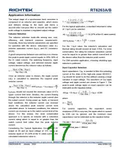
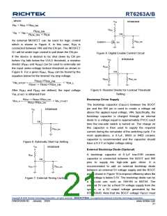
An external MOSFET can be used for logic control
which is shown in Figure 8. In this case, REN is
connected between VIN and the EN pin. The MOSFET
Q1 will be under logic control to pull down the EN pin.
R
EN_DN
Enable
Q1
Figure 8. Digital Enable Control Circuit
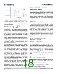
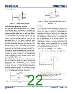
If the device is desired to be shut down by EN pin
before VIN falls below the UVLO threshold, a resistive
divider (REN1 and REN2) can be used to externally set
the input under-voltage lockout threshold as shown in
Figure 9. For a given REN1, REN2 can be found by the
equation below for the desired VIN stop voltage.
RT6263A/B
V
IN
R
EN1
EN
R
R
EN_DN
EN2
REN2//REN_DN
REN1 + REN2//REN_DN
VIN_STOP
< VEN_L
Figure 9. Resistor Divider for Lockout Threshold
Setting
After REN1 and REN2 are defined, the input voltage
VIN_START is obtained from
REN1 + REN2//REN_DN
REN2//REN_DN
Bootstrap Driver Supply
VEN_H
= V
IN_START
The bootstrap capacitor (CBOOT) between the BOOT
pin and the SW pin is used to create a voltage rail
above the applied input voltage, VIN. Specifically, the
bootstrap capacitor is charged through an internal
diode to a voltage equal to approximately PVCC each
time the low-side switch is turned on. The charge on
this capacitor is then used to supply the required
current during the remainder of the switching cycle. For
most applications, a 0.1F, 0603 or 0402 ceramic
capacitor is recommended and the capacitor should
have a 6.3 V or higher voltage rating.
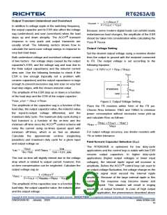
V
RT6263A/B
IN
EN
R
EN_DN
Figure 6. Automatic Start-Up Setting
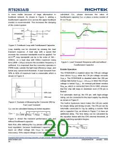
V
RT6263A/B
IN
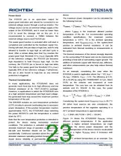
External Bootstrap Diode (Optional)
A bootstrap capacitor of 0.1F low-ESR ceramic
capacitor is connected between the BOOT and SW
pins to supply the high-side gate driver. It is
recommended to add an external bootstrap diode
between an external 5V voltage supply and the BOOT
pin as shown in Figure 10 to improve efficiency when the
input voltage is below 5.5V. The bootstrap diode can be
a low-cost one, such as 1N4148 or BAT54. The
external 5V can be a fixed 5V voltage supply from the
system, or a 5V output voltage generated by the
RT6263A/B. Note that the BOOT voltage VBOOT must
R
EN
EN
R
EN_DN
C
EN
Figure 7. External Timing Control
Copyright © 2020 Richtek Technology Corporation. All rights reserved.
is a registered trademark of Richtek Technology Corporation.
DS6263A/B-00 January 2020
www.richtek.com
21

 RICHTEK [ RICHTEK TECHNOLOGY CORPORATION ]