M51995AP/AFP
Application Note of Type M51995AP/AFP
Design of Start-up Circuit and the Power Supply of IC
1. The start-up circuit when it is not necessary to set the start and stop input voltage
Rectified DC
voltage from
smoothing capacitor
Main transformer
R1
VF
VCC
M51995A
GND
Third winding or
bias winding
+
CVCC
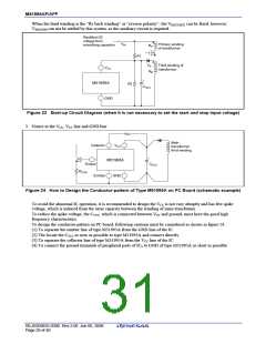
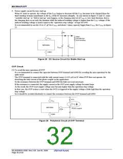
Figure 22 Start-up Circuit Diagram (when it is not necessary to set the start and stop input voltage)
Figure 22 shows one of the example circuit diagram of the start–up circuit which is used when it is not necessary to
set the start and stop voltage.
It is recommended that the current more than 300 µA flows through R1 in order to overcome the operation start-up
current ICC(START) and CVCC is in the range of 10 to 47 µF. The product of R1 by CVCC causes the time delay of
operation, so the response time will be long if the product is too much large.
Just after the start-up, the ICC current is supplied from CVCC, however, under the steady state condition, IC will be
supplied from the third winding or bias winding of transformer, the winding ratio of the third winding must be
designed so that the induced voltage may be higher than the operation-stop voltage VCC(STOP)
.
The VCC voltage is recommended to be 12 V to 17 V as the normal and optimum gate voltage is 10 to 15 V and the
output voltage (VOH) of type M51995AP/AFP is about (VCC − 2 V).
It is not necessary that the induced voltage is settled higher than the operation start-up voltage VCC(START), and the
high gate drive voltage causes high gate dissipation, on the other hand, too low gate drive voltage does not make the
MOS FET fully on-state or the saturation state.
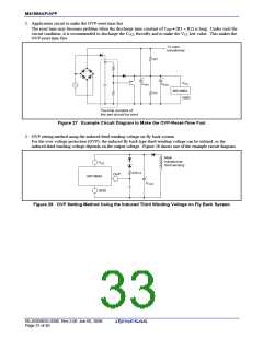
2. The start-up circuit when it is not necessary to set the start and stop input voltage
It is recommend to use the third winding of “forward winding” or “positive polarity” as shown in figure 23, when
the DC source voltages at both the IC operation start and stop must be settled at the specified values.
The input voltage (VIN(START)), at which the IC operation starts, is decided by R1 and R2 utilizing the low start-up
current characteristics of type M51995AP/AFP.
The input voltage (VIN(STOP)), at which the IC operation stops, is decided by the ratio of third winding of transformer.
The VIN(START) and VIN(STOP) are given by following equations.
R1
VIN (START) ≈ R1 × ICCL + (
+ 1) × VCC (START) ……… (9)
R2
NP
NB
1
2
VIN (STOP) ≈ (VCC (STOP) − VF) ×
+
V'IN RIP (P-P) …… (10)
Where
ICCL is the operation start-up current of IC
V
V
CC(START) is the operation start-up voltage of IC
CC(STOP) is the operation stop voltage of IC
VF is the forward voltage of rectifier diode
V’IN(P-P) is the peak to peak ripple voltage of
NB
VCC terminal ≈
V'IN RIP (P-P)
NP
It is required that the VIN(START) must be higher than VIN(STOP)
.
REJ03D0835-0300 Rev.3.00 Jun 06, 2008
Page 28 of 40

 RENESAS [ RENESAS TECHNOLOGY CORP ]