M51995AP/AFP
4. Power supply circuit for easy start-up
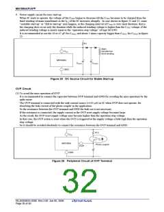
When IC starts to operate, the voltage of the CVCC begins to decrease till the CVCC becomes to be charged from the
third winding of main-transformer as the ICC of the IC increases abruptly. In case shown in figure 22 and 23, some
“unstable start-up” or “fall to start-up” may happen, as the charging interval of CVCC is very short duration; that is
the charging does occur only the duration while the induced winding voltage is higher than the CVCC voltage, if the
induced winding voltage is nearly equal to the “operation-stop voltage” of type M51995.
It is recommended to use the 10 to 47 µF for CVCC1, and about 5 times capacity bigger than CVCC1 for CVCC2 in figure
25.
R1
Main
transformer
third winding
VCC
+
+
M51995A
CVCC1
CVCC2
GND
Figure 25 DC Source Circuit for Stable Start-up
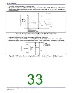
OVP Circuit
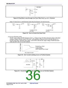
(1) To avoid the miss operation of OVP
It is recommended to connect the capacitor between OVP terminal and GND for avoiding the miss operation by the
spike noise.
The OVP terminal is connected with the sink current source (≈150 µA) in IC when OVP does not operate, for
absorbing the leak current of the photo coupler in the application.
So the resistance between the OVP terminal and GND for leak-cut is not necessary.
If the resistance is connected, the supply current at the OVP reset supply voltage becomes large.
As the result, the OVP reset supply voltage may become higher than the operation stop voltage.
In that case, the OVP action is reset when the OVP is triggered at the supply voltage a little high than the operation
stop voltage.
So it should be avoided absolutely to connect the resistance between the OVP terminal and GND.
10 k
VCC
M51995A
Photo coupler
OVP
+
GND
Figure 26 Peripheral Circuit of OVP Terminal
REJ03D0835-0300 Rev.3.00 Jun 06, 2008
Page 30 of 40

 RENESAS [ RENESAS TECHNOLOGY CORP ]