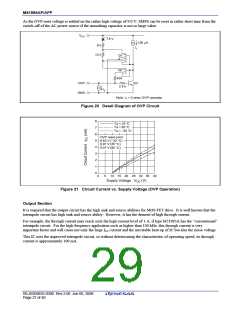
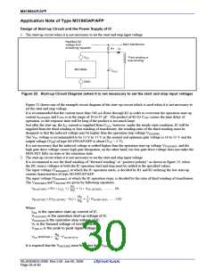
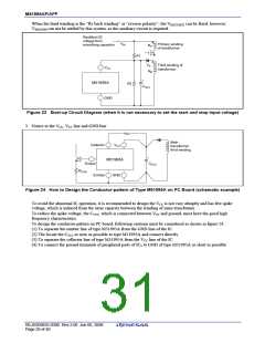
M51995AP/AFP
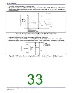
2. Application circuit to make the OVP-reset time fast
The reset time may becomes problem when the discharge time constant of CFIN • (R1 + R2) is long. Under such the
circuit condition, it is recommended to discharge the CVCC forcedly and to make the VCC low value. This makes the
OVP-reset time fast.
To main
transformer
R1
+
+
VCC
M51995A
GND
CFIN
CVCC
R2
The time constant of
this part should be short
Figure 27 Example Circuit Diagram to Make the OVP-Reset-Time Fast
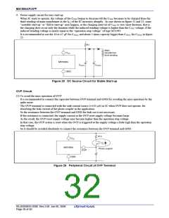
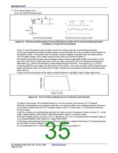
3. OVP setting method using the induced third winding voltage on fly back system
For the over voltage protection (OVP), the induced fly back type third winding voltage can be utilized, as the
induced third winding voltage depends on the output voltage. Figure 28 shows one of the example circuit diagram.
Main
transformer
third winding
VCC
470 Ω
OVP
M51995A
+
CVCC
GND
Figure 28 OVP Setting Method Using the Induced Third Winding Voltage on Fly Back System
REJ03D0835-0300 Rev.3.00 Jun 06, 2008
Page 31 of 40

 RENESAS [ RENESAS TECHNOLOGY CORP ]