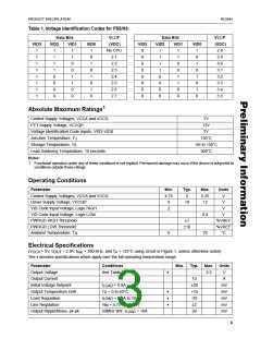
RC5041
PRODUCT SPECIFICATION
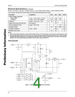
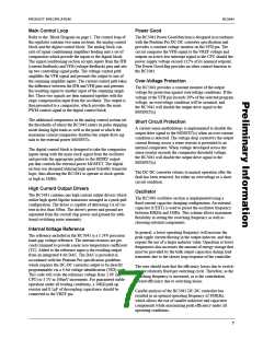
+12V
0.1µF
47Ω
1µF
t
R
t
F
VCCQP
HIDRV
+5V
VCCA
VCCD
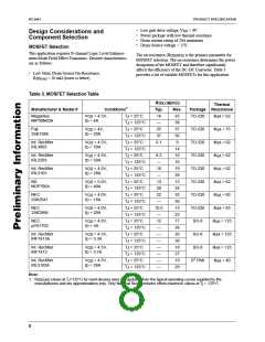
90%
50%
90%
50%
HIDRV
RISE/FALL
0.1µF
RC5041
10%
10%
7000pF
4.7µF
GNDA GNDD GNDP
65-5041-04
Figure 2. Output Driver Test Circuit
In order to obtain a more accurate approximation for V
we must also include the forward voltage V across diode
D
,
OUT
Application Information
D1 and the switching loss, Vsw. After taking into account
these factors, the new relationship becomes:
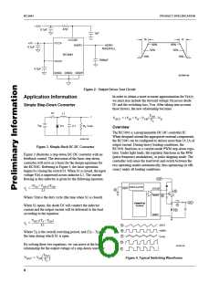
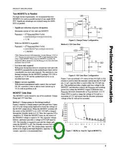
Simple Step-Down Converter
S1
L1
TON
+
RL Vout
–
----------
– VD
VOUT = (VIN + VD – VSW
)
TS
VIN
D1
C1
Overview
The RC5041 is a programmable DC-DC controller IC.
When designed around the appropriate external components,
the RC5041 can be configured to deliver more than 14.5A of
output current. During heavy loading conditions, the
RC5041 functions as a current-mode PWM step-down regu-
lator. Under light loads, the regulator functions in the PFM
(pulse frequency modulation), or pulse skipping mode. The
controller will sense the load level and switch between the
two operating modes automatically, thus optimizing its effi-
ciency under all loading conditions.
65-5041-05
Figure 3. Simple Buck DC-DC Converter
Figure 3 illustrates a step-down DC-DC converter with no
feedback control. The derivation of the basic step-down
converter will serve as a basis for the design equations for
the RC5041. Referring to Figure 3, the basic operation
begins by closing the switch S1. When S1 is closed, the input
voltage V is impressed across inductor L1. The current
IN
flowing in this inductor is given by the following equation:
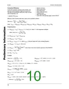
+5V
(VIN – VOUT)TON
OSCILLATOR
CEXT
IL = ----------------------------------------------
L1
VCCQP
A
D
HIDRV
GNDP
B
Where T is the duty cycle (the time when S1 is closed).
ON
VO
PWM/PFM
Control
C
When S1 opens, the diode D1 will conduct the inductor
current and the output current will be delivered to the load
according to the equation:
E
VOUT(TS – TON
IL = -------------------------------------------
L1
)
A
B
C
CEXT
HIDRV
Where T is the overall switching period, and (T – T ) is
S
S
ON
I
the time during which S1 is open.
LOAD
D
E
By solving these two equations, we can arrive at the basic
relationship for the output voltage of a step-down converter:
65-5041-06
TON
----------
VOUT = VIN
Figure 4. Typical Switching Waveforms
TS
6

 RAYTHEON [ RAYTHEON COMPANY ]