PRODUCT SPECIFICATION
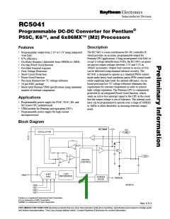
RC5041
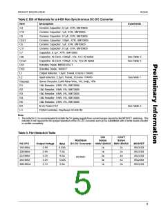
Table 2. Bill of Materials for a 4-Bit Non-Synchronous DC-DC Converter
Item
C4
Description
Comments
Ceramic Capacitor, 0.1µF, X7R, SMT0805
Ceramic Capacitor, 1µF, X7R, SMT0805
Ceramic Capacitor, 0.1µF, X7R, SMT0805
Ceramic Capacitor, 100pF, X7R, SMT0805
Ceramic Capacitor, 1µF, X7R, SMT0805
Ceramic Capacitor, 0.1µF, X7R, SMT0805
Capacitor, 0.1µF, X7R, SMT0805
C12
C8
C
EXT
C6
C11
C7
C
C
Capacitor, Al-Elect, 1200µF, 10v, 10 x 20 radial
Capacitor, Al-Elect, 1500µF, 6.3v, 10 x 20 radial
Schottky Diode, MBR2535CT
See Table 3
See Table 3
IN
OUT
DS1
DS2
L1
Schottky Diode, 1N5817
Output Inductor, 1.0µH, Toroid, 6 turns 17AWG
Input Inductor, 2.5µH, Toroid, 10 turns 17AWG
Sense Resistor, CuNi Allow Wire, 1W, 6mΩ, 10%
10Ω Resistor, 1/8W, 5%, SMT0805
10Ω Resistor, 1/8W, 5%, SMT0805
10Ω Resistor, 1/8W, 5%, SMT0805
10Ω Resistor, 1/8W, 5%, SMT0805
10Ω Resistor, 1/8W, 5%, SMT0805
N-ch Power FET
L2
See Note 1
R
SENSE
R1
R2
R3
R4
R6
M1
U1
See Table 2
PWM Controller, Raytheon RC5041M
Note:
1. The inductor L2 is recommended to isolate the 5V ipower supply from current surges caused by the MOSFET switching. This
inductor is not required for the proper operation of the DC-DC converter and can be substituted with a ferrite beads inductor
or omitter completely.
Table 3. Part Selection Table
CIN
Sanyo
COUT
Sanyo
Raytheon
K6 CPU
Output Voltage
2.9V
I
DC-DC Converter 10MV1200GX 6MV1500GX
MOSFET
IRL3103
IRL3103
IRL3103
IRL2203
IRL3103
MAX
166 MHz
200 MHz
233 MHz
266 MHz
300 MHz+
6.25A
7.5A
1x
1x
2x
3x
1x
2x
2x
4x
6x
2x
2.9V
3.2V
9.5A
RC5041
3.2V
13.0A
5.6A
2.1V
5

 RAYTHEON [ RAYTHEON COMPANY ]