VRS51L1050
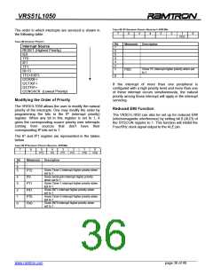
TABLE 50: IP1 INTERRUPT PRIORITY REGISTER 1–SFR B9H
The order in which interrupts are serviced is shown in
the following table:
7
6
5
4
3
2
1
PI2C
0
TABLE 48: INTERRUPT PRIORITY
Bit
7
6
Mnemonic Description
-
-
Interrupt Source
RESET (Highest Priority)
5
4
3
2
1
-
-
-
IE0
TF0
IE1
TF1
RI+TI
TF2+EXF2
Gives I²C interrupt higher priority when set
to 1
PI2C
-
0
I2CRXIF+
I2CTXIF+
I2CTFIF+
I2CNOACK (Lowest Priority)
If the interrupt of more than one peripheral is
configured with a high priority level and more than one
of these interrupt occurs simultaneously, the natural
priority among those interrupt will apply in the interrupt
servicing.
Modifying the Order of Priority
The VRS51L1050 allows the user to modify the natural
priority of the interrupts. One may modify the order by
programming the bits in the IP (interrupt priority)
register. When any bit in this register is set to 1, it
gives the corresponding source priority over interrupts
coming from sources that don’t have their
corresponding IP bits set to 1.
Reduced EMI Function
The VRS51L1050 can also be set up for reduced EMI
(electromagnetic interference) by setting bit 0 (ALEI) of
the SYSCON register to 1. This function will inhibit the
Fosc/6Hz clock signal output to the ALE pin.
The IP and IP1 register are represented in the tables
below.
TABLE 49: IP INTERRUPT PRIORITY REGISTER –SFR B8H
7
-
6
-
5
PT2
4
PS
3
PT1
2
PX1
1
PT0
0
PX0
Bit
Mnemonic Description
7
6
5
-
-
Gives Timer 2 interrupt higher priority when
set to 1
PT2
Gives serial port interrupt higher priority
when set to 1
Gives Timer 1 interrupt higher priority when
set to 1
Gives INT1 interrupt higher priority when
set to 1
Gives Timer 0 interrupt higher priority when
set to 1
4
3
2
1
0
PS
PT1
PX1
PT0
PX0
Gives INT0 interrupt higher priority when
set to 1
______________________________________________________________________________________________
www.ramtron.com page 36 of 49

 RAMTRON [ RAMTRON INTERNATIONAL CORPORATION ]