VRS51L1050
Operating Conditions
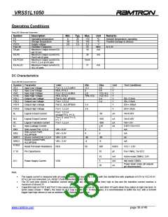
TABLE 51: OPERATING CONDITIONS
Symbol
Description
Min.
Typ.
Max.
Unit
Remarks
TA
TS
VCC5
Fosc 40
IOLpin
Operating temperature
Storage temperature
Supply voltage
Oscillator Frequency
Maximum Output current IOL
per I/O pin
0
-55
3.0
-
25
25
3.3
-
+70
155
3.3
25
ºC
ºC
V
MHz
mA
Ambient temperature, operating
Possible damage to devices
At 3.3V
10
IOLP0
Maximum Output current IOL
Port 0 all I/O pins
Maximum Output current IOL
Port 1,2,3,4 all I/O pins
Maximum Output current IOL
ALL I/O pins
26
15mA
71
mA
IOLP1234
iOLALLIO
mA
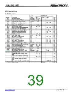
DC Characteristics
TABLE 52: DC CHARACTERISTICS
Symbol Parameter
Valid
Port 0,1,2,3,4,#EA
RES, XTAL1
Port 0,1,2,3,4,#EA
RES, XTAL1
Min.
-0.5
0
2.0
70% VCC
Max.
0.8
0.8
VCC+0.2
VCC+0.2
0.4
Unit
V
V
V
V
Test Conditions
VIL1
Input Low Voltage
Input Low Voltage
Input High Voltage
Input High Voltage
Output Low Voltage
Output Low Voltage
VIL2
VIH1
VI H2
VOL1
VOL2
Port 0, ALE, #PSEN
Port 1,2,3,4
V
V
IOL=3.2mA
IOL=1.6mA
0.4
VOH1
VOH2
Output High Voltage
Output High Voltage
Port 0, ,ALE,#PSEN
Port 1,2,3,4
2.4
2.4
V
V
IOH=-300uA
IOH=-20uA
Port 1,2,3,4
(except P1.6, P1.7)
Port 0 and P1.6,
P1.7
IIL
Logical 0 Input Current
Logical 0 Input Current
-50
uA
uA
Vin=0.45V
Vin=0.45V
IIL2
-650
ITL
ILI
Logical Transition Current
Input Leakage Current
Port 1,2,3,4
-650
+10
6
uA
uA
Vin=1.5V
0.45V<Vin<VCC
mA
ISK1
Sink current Port 1,2,3,4
Sink current Port0,
ALE,#PSEN
Source current Port 1,2,3,4
Source current Port0,
ALE,#PSEN
VIN = 0.4V
VIN = 0.4V
VIN = 2.4V
VIN = 2.4V
3
ISK2
4
8
mA
uA
ISRC1
ISRC2
R RES
-40
-4
-80
-8
mA
Reset Pull-down Resistance
Pin Capacitance
RES
50
300
10
Kohm
pF
VCC = 3.6V
C-10
Fre=1 MHz, Ta=25°C
10
5
mA
mA
uA
Active mode 25MHz, 3.6V
Idle mode 12MHz
ICC
Power Supply Current
VDD
Power down mode (all outputs
pin disconnected)
20
Note:
•
•
•
The supply current is measured with all output disconnected and XTAL1 driven with 5ns rise/fall time with amplitude of 0.5V to VCC+0.5V.
XTAL2 pin not connected, EA, RESET,Port0 connected to VDD
The I/O port pins source a transition current when they are externally driven from high to low and the transition current reaches a
maximum of around 2V.
Capacitive load on Port 0 and Port 2 may cause spurious noise to occur on ALE and other I/O ports when they output on logic low level. In
some cases (Cload > 100pF), the noise on ALE may exceed 0.8V. In those cases, it is recommended to buffer the ALE with a Schmitt
trigger type logic device or use an address with a Schmitt trigger input.
______________________________________________________________________________________________
www.ramtron.com page 38 of 49

 RAMTRON [ RAMTRON INTERNATIONAL CORPORATION ]