VRS51L1050
External Interrupts
UART Serial Port Interrupt
The VRS51L1050 has two external interrupt inputs
(INT0 and INT1). These interrupt lines are shared with
the P3.2 and P3.3 I/Os. Bits IT0 and IT1 of the TCON
register determine whether the external interrupts are
level or edge sensitive.
The serial port can generate an interrupt upon byte
reception or once the byte transmission is complete.
Those two conditions share the same interrupt vector
and it is up to the user-developed interrupt service
routine software to ascertain the cause of the interrupt
by surveying serial interrupt flags RI and TI.
o
If ITx = 1, the interrupt will be raised when a 1
to 0 transition occurs at the interrupt pin.
Note that neither of these flags is cleared by the
hardware upon execution of the interrupt service
routine. The software must clear these flags.
o
If ITx = 0, the interrupt will occur when a logic
low condition is present on the interrupt pin.
The duration of the low state must be equal to
at least 12 oscillator cycles.
I²C Interrupt
One interrupt vector is dedicated to the I²C interface.
Either one of the following events can trigger an I²C
interrupt if activated:
The state of the external interrupt, when enabled, can
be monitored using flags IE0 and IE1 of the TCON
register and will be set when the interrupt condition
occurs.
•
•
•
•
I²C data byte received (I2CRXIF)
I²C data byte transmitted (I2CTXIF)
I²C data transmission failed (I2CTFIF)
No acknowledge received (I2CNOACK)
o
If the interrupt is configured as edge sensitive,
the associated flag is automatically cleared
when the interrupt is serviced.
Once the interrupt is serviced, the program should
retrieve the I2CSTATUS register to determine which of
the events above triggered the I²C interrupt. Once the
interrupt source(s) has been identified, the
corresponding interrupt flag should be cleared.
o
If the interrupt is configured as level sensitive,
the interrupt flag must be cleared by the
software.
Timer 0 and Timer 1 Interrupt
Both Timer 0 and Timer 1 can be configured to
Execution of an Interrupt
generate an interrupt when
a
rollover of the
When the processor receives an interrupt request, an
automatic jump to the desired subroutine occurs. This
jump is similar to executing a branch to a subroutine
instruction: the processor automatically saves the
address of the next instruction on the stack.
timer/counter occurs (except Timer 0 in Mode 3). The
TF0 and TF1 flags serve to monitor timer overflow
occurring in timers 0 and 1. These interrupt flags are
automatically cleared when the interrupt is serviced.
Timer 2 interrupt
An internal flag is set to indicate that an interrupt is
taking place, and then the jump instruction is executed.
An interrupt subroutine must always end with the RETI
instruction. This instruction allows users to retrieve the
return address placed on the stack.
A Timer 2 interrupt can occur if TF2 and/or EXF2 flags
are set to 1 and if the Timer 2 interrupt is enabled. The
TF2 flag is set when a rollover of the Timer 2
Counter/Timer occurs. The EXF2 flag can be set by a
1 to 0 transition on the T2EX pin by the software.
The RETI instruction also allows updating of the
internal flag that will take into account an interrupt with
the same priority.
Note that neither flag is cleared by the hardware upon
execution of the interrupt service routine. The service
routine may have to determine whether it was TF2 or
EXF2 that generated the interrupt. These flag bits will
have to be cleared by the software.
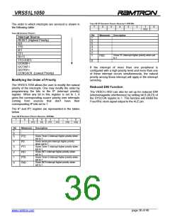
Interrupt Enable and Interrupt Priority
When the VRS51L1050 is initialized, all interrupt
sources are inhibited by resetting the bits of the IE
register to 0. It is necessary to start by enabling the
interrupt sources that the application requires by
setting bits in the IE register, as discussed previously.
Bits that generate an interrupt can be cleared or set by
the software, yielding the same result as when this
operation is done by the hardware.
This IE register is part of the bit addressable SFR. For
this reason, it is possible to modify each bit individually
in one instruction without having to modify the other
bits of the register. All interrupts can be inhibited by
setting the EA bit to 0.
______________________________________________________________________________________________
www.ramtron.com page 35 of 49

 RAMTRON [ RAMTRON INTERNATIONAL CORPORATION ]