VRS51L1050
The IF1 register holds the I²C interrupt flag.
Interrupts
TABLE 46: IF1 I2C INTERRUPT FLAG REGISTER 1–SFR A9H
The VRS51L1050 has seven interrupt sources. The
interrupts are enabled via the IE and IEN1 registers
shown below:
7
6
5
4
3
2
1
0
I2CIF
Bit
Mnemonic Description
TABLE 44: IE INTERRUPT ENABLE REGISTER –SFR A8H
7:2
1
0
-
7
EA
6
-
5
ET2
4
ES
3
ET1
2
EX1
1
ET0
0
EX0
I²C Interrupt Flag
I2CIF
-
Bit
7
Mnemonic Description
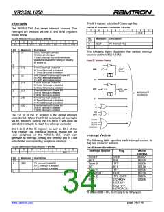
The following figure illustrates the various interrupt
sources on the VRS51L1050.
EA
Global Interrupt Controller
0: Inhibit all interrupts
1: Each interrupt source is individually
enabled or disabled by setting or clearing
its enable bit.
FIGURE 22: INTERRUPT SOURCES
6
-
-
Timer 2 Interrupt Enable Bit
0: Timer 2 interrupt is disabled
1: Timer 2 interrupt is enabled
UART Serial Port Interrupt Enable Bit
0: UART interrupt is disabled
1: UART interrupt is enabled
Timer 1 Interrupt Enable Bit
0: Timer 1 interrupt is disabled
1: Timer 1 interrupt is enabled
External Interrupt 1 Enable Bit
0: INT1 interrupt is disabled
1: INT1 interrupt is enabled
Timer 0 Interrupt Enable Bit
0: Timer 0 interrupt is disabled
1: Timer 0 interrupt is enabled
External Interrupt 0 Enable Bit
0: INT0 interrupt is disabled
1: INT0 interrupt is enabled
5
ET2
INT0
TF0
IT0
IE0
4
3
2
1
0
ES
ET1
EX1
ET0
EX0
INT1
TF1
IT1
IE1
INTERRUPT
SOURCES
T1
RI
TF2
EXF2
The EA bit of the IE register is the global interrupt
controller bit. When the EA bit is cleared, all interrupts
will be inhibited. Setting the EA bit to 1 will allow all
activated interrupts to reach the interrupt controller.
I2CRXIF
I2CTXIF
I2CTFIF
I2CNOACK
Bits 5 to 0 of the IE register, as well as bit 2 of the
IEN1 register, are individual interrupt enable bits for
each peripheral of the VRS51L1050, which can
generate an interrupt. Setting one of these bits to 1 will
activate the corresponding peripheral interrupt.
Interrupt Vectors
The following table specifies each interrupt source, its
flag and its vector address.
TABLE 45: IEN1 INTERRUPT ENABLE REGISTER 1–SFR A9H
TABLE 47: INTERRUPT VECTOR ADDRESS
7
6
5
4
3
2
1
EI2C
0
Interrupt Source
Flag
Vector
Address
0000h*
0003h
000Bh
0013h
001Bh
0023h
002Bh
003Bh
RESET
INT0
Timer 0
INT1
Timer 1
Serial Port
Timer 2
I²C
WDR
Bit
7:2
Mnemonic Description
IE0
TF0
IE1
TF1
-
I²C Interrupt Enable Bit
0: I²C interrupt is disabled
1: I²C interrupt is enabled
1
EI2C
0
-
RI+TI
TF2+EXF2
I2CRXIF+
I2CTXIF+
I2CTFIF+
I2CNOACK
*If location 0000h = FFh, the PC jump to the ISP program.
______________________________________________________________________________________________
www.ramtron.com page 34 of 49

 RAMTRON [ RAMTRON INTERNATIONAL CORPORATION ]