VRS51C1000
Serial Port Control Register
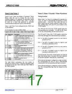
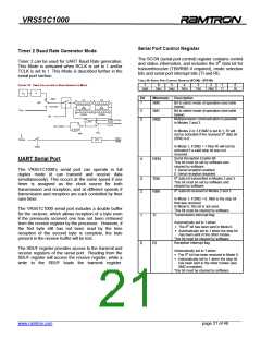
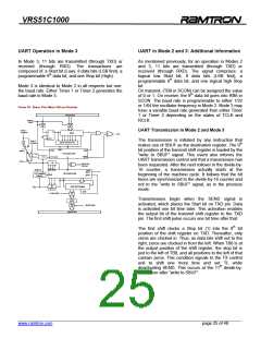
Timer 2 Baud Rate Generator Mode
The SCON (serial port control) register contains control
and status information, and includes the 9th data bit for
transmit/receive (TB8/RB8 if required), mode selection
bits and serial port interrupt bits (TI and RI).
Timer 2 can be used for UART Baud Rate generation.
This Mode is activated when RCLK is set to 1 and/or
TCLK is set to 1. This Mode is described further in the
serial port section.
TABLE 30: SERIAL PORT CONTROL REGISTER (SCON) – SFR 98H
FIGURE 15: TIMER 2 IN AUTOMATIC BAUD GENERATOR MODE
7
6
5
4
3
2
1
0
SM0
SM1
SM2
REN
TB8
RB8
TI
RI
FOSC
÷2
Bit
Mnemonic Description
0
1
TIMER
TL2
TH2
0
0
7
0
0
7
C/T2
7
6
5
SM0
SM1
SM2
Bit to select mode of operation (see table
below)
Bit to select mode of operation (see table
below)
Multiprocessor communication is possible
in Modes 2 and 3.
COUNTER
T2 pin
7
7
RCAP2L
RCAP2H
TR2
1
0
TX Clock
RX Clock
÷16
÷16
TCLK
1
0
0
1
Timer 1 Overflow
÷2
In Modes 2 or 3 if SM2 is set to 1, RI will
not be activated if the received 9th data bit
(RB8) is 0.
RCLK
SMOD
Timer 2
Interrupt
Request
T2EX pin
EXF2
In Mode 1, if SM2 = 1 then RI will not be
activated if a valid stop bit was not
received.
EXEN2
Serial Reception Enable Bit
This bit must be set by software and
cleared by software.
4
REN
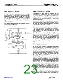
UART Serial Port
The VRS51C1000’s serial port can operate in full
duplex mode (it can transmit and receive data
simultaneously). This occurs at the same speed if one
timer is assigned as the clock source for both
transmission and reception, and at different speeds if
transmission and reception are each controlled by their
own timer.
1: Serial reception enabled
0: Serial reception disabled
9th data bit transmitted in Modes 2 and 3
This bit must be set by software and
cleared by software.
3
2
TB8
RB8
9th data bit received in Modes 2 and 3.
In Mode 1, if SM2 = 0, RB8 is the stop bit
that was received.
In Mode 0, this bit is not used.
This bit must be cleared by software.
Transmission Interrupt flag.
The VRS51C1000 serial port includes a double buffer
for the reciever, which allows reception of a byte even
if the previously received one has not been retrieved
from the receive register by the processor. However, if
the first byte still has not been read by the time
reception of the second byte is complete, the byte
present in the receive buffer will be lost.
1
0
TI
Automatically set to 1 when:
• The 8th bit has been sent in Mode 0.
• Automatically set to 1 when the stop bit
has been sent in the other modes.
This bit must be cleared by software.
Reception Interrupt flag
RI
The SBUF register provides access to the transmit and
receive registers of the serial port. Reading from the
SBUF register will access the receive register, while a
write to the SBUF loads the transmit register.
Automatically set to 1 when:
• The 8th bit has been received in Mode 0.
• Automatically set to 1 when the stop bit
has been sent in the other modes (see
SM2 exception).
This bit must be cleared by software.
______________________________________________________________________________________________
www.ramtron.com page 21 of 48

 RAMTRON [ RAMTRON INTERNATIONAL CORPORATION ]