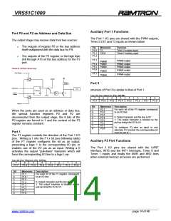
VRS51C1000
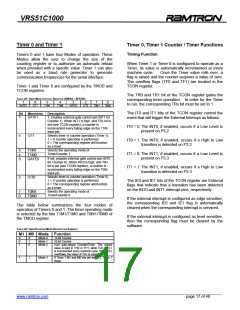
TABLE 27: TIMER 0 AND 1 CONTROL REGISTER (TCON) –SFR 88H
to 1. The count value is validated as soon as TRx goes
to 1 and the GATE bit is 0, or when INTx is 1.
7
6
TR1
5
TF0
4
TR0
3
IE1
2
IT1
1
IE0
0
IT0
TF1
Bit
7
Mnemonic Description
FIGURE 10: TIMER/COUNTER 1 MODE 0: 13-BIT COUNTER
TF1
Timer 1 Overflow Flag. Set by hardware on
Timer/Counter overflow. Cleared by
hardware on Timer/Counter overflow.
Cleared by hardware when processor
vectors to interrupt routine.
÷12
Fosc
TL1 / TL0
0
1
C/T1 / C/T0 =0
C/T1 / CT0 =1
0
4
7
CLK
6
TR1
TF0
Timer 1 Run Control Bit. Set/cleared by
software to turn Timer/Counter on or off.
Timer 0 Overflow Flag. Set by hardware on
Timer/Counter overflow. Cleared by
hardware when processor vectors to
interrupt routine.
Mode 0
Mode 1
Control
T1/T0 pin
TR1/TR0
5
TH1 / TH0
GATE1 /
GATE0
0
7
Timer 0 Run Control Bit. Set/cleared by
software to turn Timer/Counter on or off.
Interrupt Edge Flag. Set by hardware when
external interrupt edge is detected. Cleared
when interrupt processed.
4
3
TR0
IE1
INT1 /
INT0 pin
TF1 /
TF0
INT
Interrupt 1 Type Control Bit. Set/cleared by
software to specify falling edge/low level
triggered external interrupts.
Interrupt 0 Edge Flag. Set by hardware
when external interrupt edge is detected.
Cleared when interrupt processed.
Interrupt 0 Type control bit. Set/cleared by
software to specify falling edge/low level
triggered external interrupts.
2
1
0
IT1
IE0
IT0
Mode 1
Mode 1 is almost identical to Mode 0, with the
difference being that in Mode 1, the counter/timer uses
the full 16-bits of the Timer.
Mode 2
In this Mode, the register of the Timer is configured as
an 8-bit auto-re-loadable Counter/Timer. In Mode 2,
the TLx is used as the counter. In the event of a
counter overflow, the TFx flag is set to 1 and the value
contained in THx, which is preset by software, is
reloaded into the TLx counter. The value of THx
remains unchanged.
Counting Function
When operating as a counter, the Timer’s register is
incremented at every falling edge of the T0 and T1
signals located at the input of the timer.
When the sampling circuit sees a high immediately
followed by a low in the next machine cycle, the
counter is incremented. Two machine cycles are
required to detect and record an event. In order to be
properly sampled, the duration of the event presented
to the Timer input should be greater than 1/24 of the
oscillator frequency.
FIGURE 11: TIMER/COUNTER 1 MODE 2: 8-BIT AUTOMATIC RELOAD
Fosc
÷12
C/T1 / C/T0 = 1
C/T1 / C/T0 = 1
TL1 / TL0
0
1
0
7
Control
T1 / T0 Pin
Reload
Timer 0 / Timer 1 Operating Modes
0
7
The user may change the operating mode by setting
the M1 and M0 bits of the TMOD SFR.
TH1 / TH0
TF1 / TF0
TR1 / TR0
GATE1 / GATE0
Mode 0
INT
INT1 / INT0 pin
A schematic representation of this mode of operation is
presented in the figure below. In Mode 0, the Timer
operates as 13-bit counter made up of 5 LSBs from the
TLx register and the 8 upper bits coming from the THx
register. When an overflow causes the value of the
register to roll over to 0, the TFx interrupt signal goes
______________________________________________________________________________________________
www.ramtron.com page 18 of 48

 RAMTRON [ RAMTRON INTERNATIONAL CORPORATION ]