VRS51C1000
Serial Port Receive Clock Source.
1: Causes Serial Port to use Timer 2
overflow pulses for its receive clock in
Modes 1 and 3.
5
4
3
RCLK
TCLK
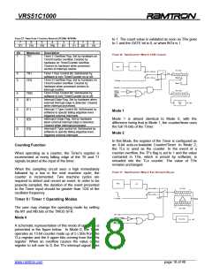
Mode 3
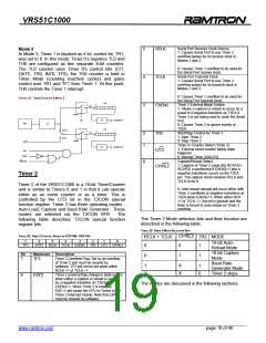
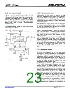
In Mode 3, Timer 1 is blocked as if its’ control bit, TR1,
was set to 0. In this mode, Timer 0’s registers TL0 and
TH0 are configured as two separate 8-bit counters.
The TL0 counter uses Timer 0’s control bits (C/T,
GATE, TR0, INT0, TF0), the TH0 counter is held in
Timer Mode (counting machine cycles) and gains
control over TR1 and TF1 from Timer 1. At this point,
TH0 controls the Timer 1 interrupt.
0: Causes Timer 1 overflow to be used for
the Serial Port receive clock.
Serial Port Transmit Clock.
1: Causes Serial Port to use Timer 2
overflow pulses for its transmit clock in
Modes 1 and 3.
0: Causes Timer 1 overflow to be used for
the Serial Port transmit clock.
Timer 2 External Mode Enable.
1: Allows a capture or reload to occur as a
result of a negative transition on T2EX if
Timer 2 is not being used to clock the Serial
Port.
FIGURE 12: TIMER/COUNTER 0 MODE 3
TH0
0
7
EXEN2
CLK
Control
TF1
INTERRUPT
TR1
Fosc
÷12
0: Causes Timer 2 to ignore events at
T2EX.
Start/Stop Control for Timer 2.
1: Start Timer 2
TL0
0
1
C/T =0
C/T =1
0
7
CLK
2
1
TR2
Control
0: Stop Timer 2
T0PIN
Timer or Counter Select (Timer 2)
1: External event counter falling edge
triggered.
TF0
INTERRUPT
C/T2
TR0
GATE
0: Internal Timer (OSC/12)
INT0 PIN
Capture/Reload Select.
0
1: Capture of Timer 2 value into RCAP2H,
RCAP2L is performed if EXEN2=1 and a
negative transitions occurs on the T2EX
pin. The capture mode requires RCLK and
TCLK to be 0.
CP/RL2
Timer 2
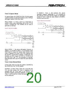
Timer 2 of the VRS51C1000 is a 16-bit Timer/Counter
and is similar to Timers 0 and 1 in that it can operate
either as an event counter or as a timer. This is
controlled by the C/T2 bit in the T2CON special
function register. Timer 2 has three operating modes -
Auto-Load, Capture and Baud Rate Generator. These
0: Auto-reload reloads will occur either with
Timer 2 overflows or negative transitions at
T2EX when EXEN2=1. When either RCK
=1 or TCLK =1, this bit is ignored and the
timer is forced to auto-reload on Timer 2
overflow.
modes are selected via the T2CON SFR.
following table describes T2CON special function
register bits.
The
The Timer 2 Mode selection bits and their function are
described in the following table.
TABLE 29: TIMER 2 MODE SELECTION BITS
TABLE 28: TIMER 2 CONTROL REGISTER (T2CON) –SFR C8H
CP/RL2
0
RCLK + TCLK
0
TR2 MODE
7
TF2
6
EXF2
5
4
3
2
1
C/T2
0
16-bit Auto-
RCLK
TCLK
EXEN2
TR2
CP/RL2
1
1
Reload Mode
16-bit Capture
Mode
Bit
Mnemonic Description
0
1
Timer 2 Overflow Flag: Set by an overflow
of Timer 2 and must be cleared by
software. TF2 will not be set when either
RCLK =1 or TCLK =1.
7
TF2
Baud Rate
Generator Mode
Timer 2 stops
1
X
X
1
0
X
Timer 2 external flag change in state occurs
when either a capture or reload is caused
by a negative transition on T2EX and
EXEN2=1. When Timer 2 is enabled,
EXF=1 will cause the CPU to Vector to the
Timer 2 interrupt routine. Note that EXF2
must be cleared by software.
6
EXF2
The modes are discussed in the following sections.
______________________________________________________________________________________________
www.ramtron.com page 19 of 48

 RAMTRON [ RAMTRON INTERNATIONAL CORPORATION ]