VRS51C1000
Timer 0, Timer 1 Counter / Timer Functions
Timer 0 and Timer 1
Timing Function
Timers 0 and 1 have four Modes of operation. These
Modes allow the user to change the size of the
counting register or to authorize an automatic reload
when provided with a specific value. Timer 1 can also
be used as a baud rate generator to generate
communication frequencies for the serial interface.
When Timer 1 or Timer 0 is configured to operate as a
Timer, its value is automatically incremented at every
machine cycle.
flag is raised and the counter acquires a value of zero.
The overflow flags (TF0 and TF1) are located in the
TCON register.
Once the Timer value rolls over, a
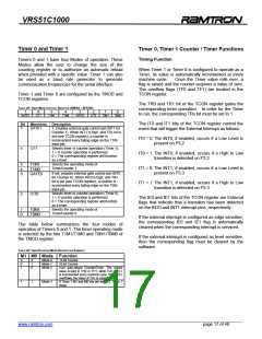
Timer 1 and Timer 0 are configured by the TMOD and
TCON registers.
The TR0 and TR1 bit of the TCON register gates the
corresponding timer operation. In order for the Timer
to run, the corresponding TRx bit must be set to 1.
TABLE 25: TIMER MODE CONTROL REGISTER (TMOD) – SFR 89H
7
6
C/T1
5
T1M1
4
T1M0
3
2
C/T0
1
T0M1
0
T0M0
GATE1
GATE0
The IT0 and IT1 bits of the TCON register control the
event that will trigger the External Interrupt as follows:
Bit
7
Mnemonic Description
GATE1
C/T1
1: Enables external gate control (pin INT1 for
Counter 1). When INT1 is high, and TRx bit is
set (see TCON register), a counter is
incremented every falling edge on the T1IN
input pin.
Selects timer or counter operation (Timer 1).
1 = A counter operation is performed
0 = The corresponding register will function
as a timer.
IT0 = 0: The INT0, if enabled, occurs if a Low Level is
present on P3.2
6
IT0 = 1: The INT0, if enabled, occurs if a High to Low
transition is detected on P3.2
Selects the operating mode of
Timer/Counter 1
5
4
3
T1M1
T1M0
GATE0
IT1 = 0: The INT1, if enabled, occurs if a Low Level is
present on P3.3
If set, enables external gate control (pin INT0
for Counter 0). When INT0 is high, and TRx
bit is set (see TCON register), a counter is
incremented every falling edge on the T0IN
input pin.
IT1 = 1: The INT1, if enabled, occurs if a High to Low
transition is detected on P3.3
Selects timer or counter operation (Timer 0).
1 = A counter operation is performed
0 = The corresponding register will function
as a timer.
Selects the operating mode of
Timer/Counter 0.
2
C/T0
The IE0 and IE1 bits of the TCON register are External
flags that indicate that a transition has been detected
on the INT0 and INT1 interrupt pins, respectively.
1
0
T0M1
T0M0
If the external interrupt is configured as edge sensitive,
the corresponding IE0 and IE1 flag is automatically
cleared when the corresponding interrupt is serviced.
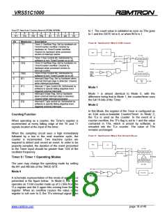
The table below summarizes the four modes of
operation of Timers 0 and 1. The timer operating mode
is selected by the bits T1M1/T1M0 and T0M1/T0M0 of
the TMOD register.
If the external interrupt is configured as level sensitive,
then the corresponding flag must be cleared by the
software.
TABLE 26: TIMER/COUNTER MODE DESCRIPTION SUMMARY
M1 M0 Mode Function
0
0
1
0
1
0
Mode 0
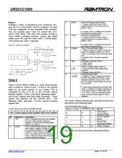
Mode 1
Mode 2
13-bit Counter
16-bit Counter
8-bit auto-reload Counter/Timer. The reload
value is kept in TH0 or TH1, while TL0 or TL1
is incremented every machine cycle. When TLx
overflows, the value of THx is copied to TLx.
If Timer 1 M1 and M0 bits are set to 1, Timer 1
stops.
1
1
Mode 3
______________________________________________________________________________________________
www.ramtron.com page 17 of 48

 RAMTRON [ RAMTRON INTERNATIONAL CORPORATION ]