Functional Overview
PLX Technology, Inc.
4.3.1
PEX 8532 Functional Blocks
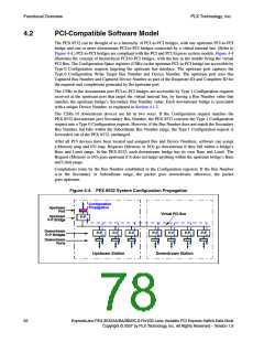
At the top level, each station has a layered organization consisting of the Physical (PHY), Data Link
Layer (DLL), and Transaction Layer Control (TLC) blocks, as illustrated in Figure 4-6. The PHY and
DLL blocks have port-specific data paths (one per PCI Express port) that operate independently of one
another. The TLC ingress aggregates traffic for all ingress ports in the station, then sends the traffic to
the internal fabric. The TLC egress accepts packets, by way of the internal fabric, from all ingress ports,
and schedules them to be sent out the appropriate egress port.
Figure 4-6. PCI Express Station Block Diagram
Non-Blocking Internal Fabric
Transaction Layer Control
TLC Ingress
TLC Egress
CSR
Handling
Ingress Credit
Egress Credit
Unit
Unit
Data Link Layer
Physical Layer
DLL Ingress 0-3
DLL Egress 0-3
Port Receive Logic
Port
Enum.
Logic
Link Receive and Transmit Logic
16 Serial Lanes
60
ExpressLane PEX 8532AA/BA/BB/BC 8-Port/32-Lane Versatile PCI Express Switch Data Book
Copyright © 2007 by PLX Technology, Inc. All Rights Reserved – Version 1.6

 PLX [ PLX TECHNOLOGY ]