Philips Semiconductors
Preliminary specification
Stereo audio codec with SPDIF interface
UDA1355H
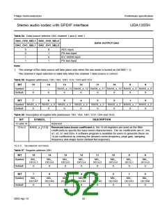
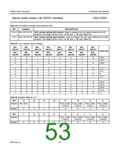
Table 58 Description of register bits (address 20H)
BIT
SYMBOL
DESCRIPTION
15 to 8 MA_DECL[7:0]
ADC volume setting left channel. Value to program the ADC gain setting for the left
channel. The range is from +24 to −63 dB and −∞ dB (see Table 59).
7 to 0 MA_DECR[7:0] ADC volume setting right channel. Value to program the ADC gain setting for the right
channel. The range is from +24 to −63 dB and −∞ dB (see Table 59).
Table 59 ADC volume control settings
MA_
MA_
MA_
MA_
MA_
MA_
MA_
MA_
DECL7
DECL6
DECL5
DECL4
DECL3
DECL2
DECL1
DECL0
GAIN (dB)
MA_
MA_
MA_
MA_
MA_
MA_
MA_
MA_
DECR7
DECR6
DECR5
DECR4
DECR3
DECR2
DECR1
DECR0
0
0
0
:
0
0
0
:
1
1
1
:
1
0
0
:
0
1
1
:
0
1
1
:
0
1
1
:
0
1
0
:
+24.0
+23.5
+23.0
:
0
0
0
1
:
0
0
0
1
:
0
0
0
1
:
0
0
0
1
:
0
0
0
1
:
0
0
0
1
:
1
0
0
1
:
0
1
0
1
:
+1.0
+0.5
0
−0.5
:
1
1
1
1
1
0
0
0
0
0
0
0
0
0
0
0
0
0
0
0
0
0
0
0
0
1
0
0
0
0
0
1
1
0
0
0
1
0
1
0
−62.0
−62.5
−63.0
−63.5
−∞
Table 60 Register address 21H
BIT
15
14
13
12
11
10
9
8
Symbol MT_ADC
−
−
−
PGA_GAIN_ PGA_GAIN_ PGA_GAIN_ PGA_GAIN_
CTRLL3
CTRLL2
CTRLL1
CTRLL0
Default
0
0
0
0
0
0
0
0
BIT
7
6
5
4
3
2
1
0
Symbol
−
−
−
−
PGA_GAIN_ PGA_GAIN_ PGA_GAIN_ PGA_GAIN_
CTRLR3
CTRLR2
CTRLR1
CTRLR0
Default
0
0
0
0
0
0
0
0
2003 Apr 10
53

 NXP [ NXP ]