Philips Semiconductors
Preliminary specification
Stereo audio codec with SPDIF interface
UDA1355H
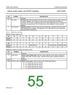
12.2.5 SPDIF OUTPUT SETTINGS
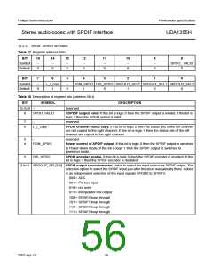
Table 67 Register address 50H
BIT
15
14
13
12
11
10
9
8
Symbol
Default
−
−
−
−
−
−
−
SPDO_ VALID
0
0
0
0
0
0
0
0
BIT
7
6
5
4
3
2
1
0
Symbol
Default
−
L_r_copy
1
−
PON_SPDO DIS_SPDO SPDOUT_SEL2 SPDOUT_SEL1 SPDOUT_SEL0
0
0
1
0
1
0
0
Table 68 Description of register bits (address 50H)
BIT
SYMBOL
DESCRIPTION
15 to 9
8
−
reserved
SPDO_VALID
SDPDIF output valid. If this bit is logic 0 then the SPDIF output is invalid; if this bit is
logic 1 then the SPDIF output is valid.
7
6
−
reserved
L_r_copy
SPDIF channel status copy. If this bit is logic 0 then the status bits of the left channel
are not copied to the right channel; if this bit is logic 1 then the status bits of the left
channel are copied to the right channel.
5
4
−
reserved
PON_SPDO
Power control of SPDIF output. If this bit is logic 0 then the SPDIF output is switched
to Power-down mode; if this bit is logic 1 then the SPDIF output is switched to
power-on mode.
3
DIS_SPDO
SPDIF encoder enable. If this bit is logic 0 then the SPDIF encoder is enabled; if this
bit is logic 1 then the SPDIF encoder is disabled.
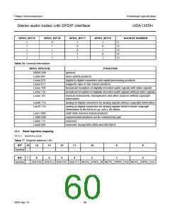
2 to 0 SPDOUT_SEL[2:0] SPDIF output source selector. Value to select the input source for SPDIF output. The
selection option to select the SPDIF input just after the slicer was already there. Added
is an independent selection of the input signals SPDIF0 to SPDIF3:
000 = ADC
001 = I2S-bus input
010 = not used
011 = interpolator mix output
100 = SPDIF0 loop through
101 = SPDIF1 loop through
110 = SPDIF2 loop through
111 = SPDIF3 loop through
2003 Apr 10
56

 NXP [ NXP ]