Philips Semiconductors
Preliminary specification
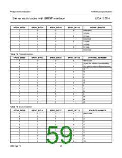
Stereo audio codec with SPDIF interface
UDA1355H
BIT
SYMBOL
DESCRIPTION
11 to 2
1
−
reserved
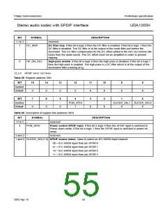
DC_SKIP
DC filter skip. If this bit is logic 0 then the DC filter is enabled; if this bit is logic 1 then the
DC filter is disabled. The DC filter is at the output of the comb filter just before the
decimator. This DC filter compensates for the DC offset added in the ADC (to remove idle
tones from the audio band). This DC offset must not be amplified in order to prevent
clipping.
0
HP_EN_DEC
High-pass enable. If this bit is logic 0 then the high-pass is disabled; if this bit is logic 1
then the high-pass is enabled. The high-pass is a DC filter which is at the output of the
decimation filter (running at fs).
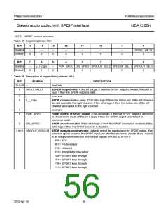
12.2.4 SPDIF INPUT SETTINGS
Table 65 Register address 30H
BIT
15
14
13
12
11
10
9
8
Symbol
Default
−
−
−
−
−
−
−
−
0
0
0
0
0
0
0
0
BIT
7
6
5
4
3
2
1
0
Symbol
Default
−
−
−
PON_SPDI
1
−
−
SLICER_SEL1 SLICER_SEL0
0
0
0
0
0
0
0
Table 66 Description of register bits (address 30H)
BIT
SYMBOL
DESCRIPTION
15 to 5
4
−
reserved
PON_SPDI
Power control SPDIF input. If this bit is logic 0 then the SPDIF input is switched to
Power-down mode; if this bit is logic 1 then the SPDIF input is switched to power-on
mode.
3 and 2
−
reserved
1 and 0 SLICER_SEL[1:0] SPDIF source select. Value to select an IEC 60958 input channel:
00 = IEC 60958 input from pin SPDIF0
01 = IEC 60958 input from pin SPDIF1
10 = IEC 60958 input from pin SPDIF2
11 = IEC 60958 input from pin SPDIF3
2003 Apr 10
55

 NXP [ NXP ]