Philips Semiconductors
Preliminary specification
Stereo audio codec with SPDIF interface
UDA1355H
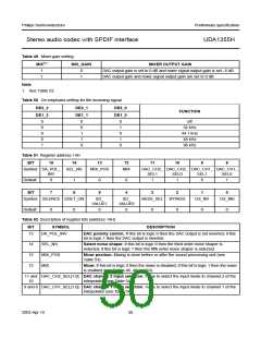
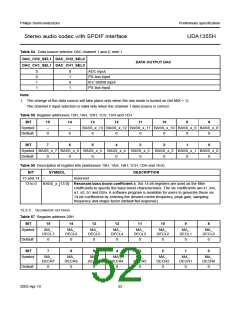
Table 54 Data source selector DAC channel 1 and 2; note 1
DAC_CH2_SEL1 DAC_CH2_SEL0
DATA OUTPUT DAC
DAC_CH1_SEL1 DAC_CH1_SEL0
0
0
1
1
0
1
0
1
ADC input
I2S-bus input
IEC 60958 input
I2S-bus input
Note
1. The change of the data source will take place only when the mix mode is turned on (bit MIX = 1).
The channel 2 input selection is valid only when the channel 1 data source is correct.
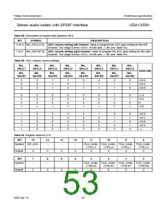
Table 55 Register addresses 19H, 1AH, 1BH, 1CH, 1DH and 1EH
BIT
15
14
13
12
11
10
9
8
Symbol
Default
−
−
BASS_x_13 BASS_x_12 BASS_x_11 BASS_x_10 BASS_x_9 BASS_x_8
0
0
0
0
0
0
0
0
BIT
7
6
5
4
3
2
1
0
Symbol BASS_x_7 BASS_x_6 BASS_x_5 BASS_x_4 BASS_x_3 BASS_x_2 BASS_x_1 BASS_x_0
Default
0
0
0
0
0
0
0
0
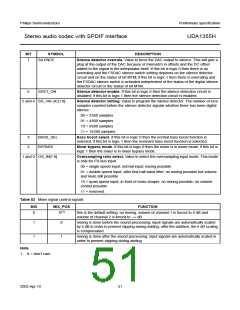
Table 56 Description of register bits (addresses 19H, 1AH, 1BH, 1CH, 1DH and 1EH)
BIT
SYMBOL
DESCRIPTION
15 and 14
13 to 0
−
reserved
BASS_x_[13:0] Resonant bass boost coefficient x. Six 14-bit registers are used as the filter
coefficients to specify the bass boost characteristics. The six coefficients are k1, km,
a1, a2, b1 and b2m. A software program is available for users to generate these six
14-bit coefficients by entering the desired centre frequency, peak gain, sampling
frequency and shape factor (default flat response).
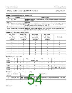
12.2.3 DECIMATOR SETTINGS
Table 57 Register address 20H
BIT
15
14
13
12
11
10
9
8
Symbol
MA_
MA_
MA_
MA_
MA_
MA_
MA_
MA_
DECL7
DECL6
DECL5
DECL4
DECL3
DECL2
DECL1
DECL0
Default
0
0
0
0
0
0
0
0
BIT
7
6
5
4
3
2
1
0
Symbol
MA_
MA_
MA_
MA_
MA_
MA_
MA_
MA_
DECR7
DECR6
DECR5
DECR4
DECR3
DECR2
DECR1
DECR0
Default
0
0
0
0
0
0
0
0
2003 Apr 10
52

 NXP [ NXP ]