Philips Semiconductors
Preliminary specification
Stereo audio codec with SPDIF interface
UDA1355H
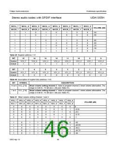
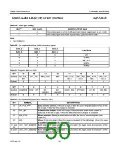
Table 49 Mixer gain setting
MIX(1)
MIX_GAIN
MIXER OUTPUT GAIN
1
1
0
1
DAC output gain is set to 0 dB and mixer signal output gain is set −6 dB
DAC output gain and mixer signal output gain are set to 0 dB
Note
1. See Table 52.
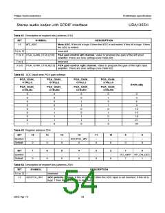
Table 50 De-emphasis setting for the incoming signal
DE2_2
DE1_2
DE2_1
DE1_1
DE2_0
DE1_0
FUNCTION
0
0
0
0
1
0
0
1
1
0
0
1
0
1
0
off
32 kHz
44.1 kHz
48 kHz
96 kHz
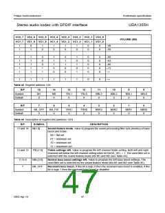
Table 51 Register address 14H
BIT 15 14
13
12
11
10
9
8
Symbol DA_POL_ SEL_NS
INV
MIX_POS
MIX
DAC_CH2_ DAC_CH2_ DAC_CH1_ DAC_CH1_
SEL1
1
SEL0
1
SEL1
0
SEL0
1
Default
0
1
0
0
BIT
7
6
5
4
3
2
1
0
Symbol SILENCE SDET_ON
SD_
SD_
BASS_SEL
BYPASS
OS_IN1
OS_IN0
VALUE1
VALUE0
Default
0
0
0
0
0
0
0
0
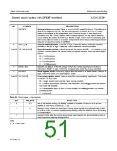
Table 52 Description of register bits (address 14H)
BIT
SYMBOL
DESCRIPTION
15
DA_POL_INV
DAC polarity control. If this bit is logic 0 then the DAC output is not inverted; if this
bit is logic 1 then the DAC output is inverted.
14
13
12
SEL_NS
MIX_POS
MIX
Select noise shaper. If this bit is logic 0 then the third order noise shaper is
selected; if this bit is logic 1 then the fifth order noise shaper is selected.
Mixer position. Mixing is done before or after the sound processing unit (see
Table 53).
Mixer. If this bit is logic 0 then the mixer is disabled; if this bit is logic 1 then the mixer
is enabled (see Tables 48, 49 and 53).
11 and DAC_CH2_SEL[1:0] DAC channel 2 input selection. Value to select the input mode to channel 2 of the
10 interpolator (see Table 54).
9 and 8 DAC_CH1_SEL[1:0] DAC channel 1 input selection. Value to select the input mode to channel 1 of the
interpolator (see Table 54).
2003 Apr 10
50

 NXP [ NXP ]