Philips Semiconductors
Preliminary specification
Stereo audio codec with SPDIF interface
UDA1355H
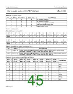
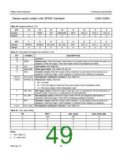
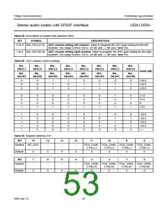
Table 46 Register address 13H
BIT
Symbol
Default
15
14
13
12
11
10
9
8
−
MTM
0
GS
0
MIXGAIN
0
MT2
1
DE2_2
0
DE2_1
0
DE2_0
0
0
BIT
7
6
5
4
3
2
1
0
Symbol
Default
MTNS1
0
MTNS0
0
WS_SEL
0
DE_SW
0
MT1
0
DE1_2
0
DE1_1
0
DE1_0
0
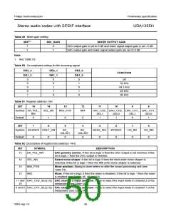
Table 47 Description of register bits (address 13H)
BIT
SYMBOL
DESCRIPTION
15
14
-
reserved
MTM
Master mute. If this bit is logic 0 then there is no master mute or the master de-mute is in
progress; if this bit is logic 1 then the master mute is in progress or muted.
13
12
11
GS
Gain select. See Table 48.
MIXGAIN
MT2
Mixer gain select. See Tables 48 and 49.
Channel 2 mute. If this bit is logic 0 then channel 2 is not muted or the de-mute is in
progress; if this bit is logic 1 then channel 2 is muted or the muting is in progress.
10 to 8
7 and 6
DE2_[2:0] De-emphasis setting for channel 2. See Table 50.
MTNS[1:0] Interpolator mute. Selection:
00 = no mute
01 = if no WS signal is detected, the noise shaper of the interpolator mute
1x = the noise shaper of the interpolator mute
5
4
WS_SEL
DE_SW
MT1
WS signal select. If this bit is logic 0 then WS_DET is selected for the WS detection; if
this bit is logic 1 then FPLL is selected for the WS detection.
De-emphasis select. If this bit is logic 0 then SPDIF pre-emphasis information is
selected; if this bit is logic 1 then the de-emphasis setting is selected.
3
Channel 1 mute. If this bit is logic 0 then channel 1 is not muted or the de-mute is in
progress; if this bit is logic 1 then channel 1 is muted or the muting is in progress.
2 to 0
DE1_[2:0] De-emphasis setting for channel 1. See Table 50.
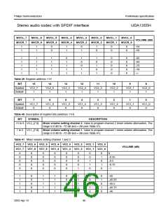
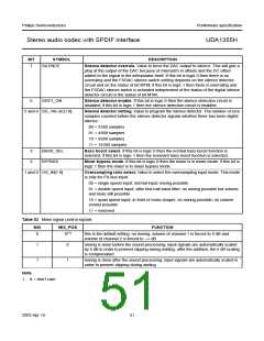
Table 48 DAC gain setting
GS
MIX(1)
MIX_GAIN
DAC GAIN (dB)
0
1
1
1
1
X(2)
0
X(2)
0
0
6
0
6
6
1
0
0
1
1
1
Notes
1. See Table 52.
2. X = don’t care
2003 Apr 10
49

 NXP [ NXP ]