Philips Semiconductors
Preliminary specification
Stereo audio codec with SPDIF interface
UDA1355H
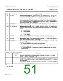
BIT
SYMBOL
SILENCE
DESCRIPTION
7
Silence detector overrule. Value to force the DAC output to silence. This will give a
plop at the output of the DAC because of mismatch in offsets and the DC offset
added to the signal in the interpolator itself. If this bit is logic 0 then there is no
overruling and the FSDAC silence switch setting depends on the silence detector
circuit and on the status of bit MTM; if this bit is logic 1 then there is overruling and
the FSDAC silence switch is activated independent of the status of the digital silence
detector circuit or the status of bit MTM.
6
SDET_ON
Silence detector enable. If this bit is logic 0 then the silence detection circuit is
disabled; if this bit is logic 1 then the silence detection circuit is enabled.
5 and 4 SD_VALUE[1:0]
Silence detector setting. Value to program the silence detector. The number of zero
samples counted before the silence detector signals whether there has been digital
silence:
00 = 3200 samples
01 = 4800 samples
10 = 9600 samples
11 = 19200 samples
3
2
BASS_SEL
BYPASS
Bass boost select. If this bit is logic 0 then the normal bass boost function is
selected; if this bit is logic 1 then the resonant bass boost function is selected.
Mixer bypass mode. If this bit is logic 0 then the mixer is in mixer mode; if this bit is
logic 1 then the mixer is in mixer bypass mode.
1 and 0 OS_IN[1:0]
Oversampling ratio select. Value to select the oversampling input mode. This mode
is only for I2S-bus input:
00 = single speed input; normal input; mixing possible
01 = double speed input; after first half-band filter; no mixing possible but volume
and mute still possible
10 = quad speed input; in front of noise shaper; no mixing possible; no volume
control possible
11 = reserved.
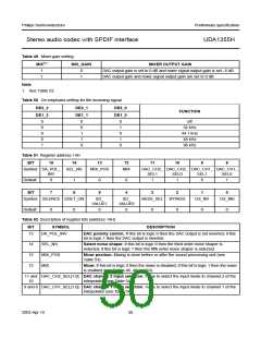
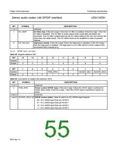
Table 53 Mixer signal control signals
MIX
MIX_POS
FUNCTION
0
X(1)
this is the default setting: no mixing, volume of channel 1 is forced to 0 dB and
volume of channel 2 is forced to −∞ dB
1
1
0
1
mixing is done before the sound processing; input signals are automatically scaled
by 6 dB in order to prevent clipping during adding; after the addition, the 6 dB scaling
is compensated
mixing is done after the sound processing; input signals are automatically scaled in
order to prevent clipping during adding
Note
1. X = don’t care
2003 Apr 10
51

 NXP [ NXP ]