Philips Semiconductors
Preliminary specification
Stereo audio codec with SPDIF interface
UDA1355H
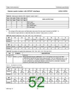
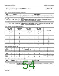
Table 61 Description of register bits (address 21H)
BIT
SYMBOL
MT_ADC
DESCRIPTION
15
Mute ADC. If this bit is logic 0 then the ADC is not muted; if this bit is logic 1 then
the ADC is muted.
14 to 12 −
reserved
11 to 8 PGA_GAIN_CTRLL[3:0] PGA gain control left channel. Value to program the gain of the left input
amplifier. There are nine settings (see Table 62).
7 to 4
−
reserved
3 to 0 PGA_GAIN_CTRLR[3:0] PGA gain control right channel. Value to program the gain of the right input
amplifier. There are nine settings (see Table 62).
Table 62 ADC input amp PGA gain settings
PGA_GAIN_
CTRLL3
PGA_GAIN_
CTRLL2
PGA_GAIN_
CTRLL1
PGA_GAIN_
CTRLL0
GAIN (dB)
PGA_GAIN_
CTRLR3
PGA_GAIN_
CTRLR2
PGA_GAIN_
CTRLR1
PGA_GAIN_
CTRLR0
0
0
0
0
0
0
0
0
1
0
0
0
0
1
1
1
1
0
0
0
1
1
0
0
1
1
0
0
1
0
1
0
1
0
1
0
0
3
6
9
12
15
18
21
24
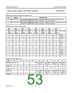
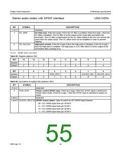
Table 63 Register address 22H
BIT
15
14
13
12
11
10
9
8
Symbol
Default
−
−
−
ADCPOL_INV
0
−
−
−
−
0
0
0
0
0
0
0
BIT
7
6
5
4
3
2
1
0
Symbol
Default
−
−
−
−
−
−
DC_SKIP HP_EN_DEC
0
0
0
0
0
0
1
1
Table 64 Description of register bits (address 22H)
BIT
SYMBOL
DESCRIPTION
15 to 13 −
reserved
12
ADCPOL_INV
ADC polarity control. If this bit is logic 0 then the ADC input is not inverted; if this bit is
logic 1 then the ADC input is inverted.
2003 Apr 10
54

 NXP [ NXP ]