Philips Semiconductors
Preliminary specification
Stereo audio codec with SPDIF interface
UDA1355H
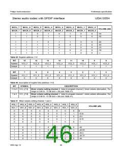
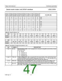
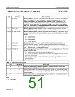
VC2_7 VC2_6 VC2_5 VC2_4 VC2_3 VC2_2 VC2_1 VC2_0
VC1_7 VC1_6 VC1_5 VC1_4 VC1_3 VC1_2 VC1_1 VC1_0
VOLUME (dB)
1
1
:
0
1
:
1
0
:
1
0
:
1
0
:
1
0
:
0
0
:
0
0
:
−48
−50
:
1
1
1
1
1
:
1
1
1
1
1
:
0
0
0
1
1
:
1
1
1
0
0
:
0
1
1
0
0
:
1
0
1
0
1
:
0
0
0
0
0
:
0
0
0
0
0
:
−60
−63
−66
−72
−∞
:
1
1
1
1
1
1
0
0
−∞
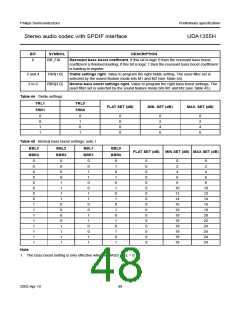
Table 42 Register address 12H
BIT
Symbol
Default
15
M1
0
14
M0
0
13
12
TRL0
0
11
BBL3
0
10
BBL2
0
9
BBL1
0
8
BBL0
0
TRL1
0
BIT
7
6
5
4
3
2
1
0
Symbol
Default
BB_OFF
0
BB_FIX
0
TRR1
0
TRR0
0
BBR3
0
BBR2
0
BBR1
0
BBR0
0
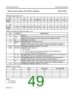
Table 43 Description of register bits (address 12H)
BIT
SYMBOL
DESCRIPTION
15 and 14
M[1:0]
Sound feature mode. Value to program the sound processing filter sets (modes) of bass
boost and treble:
00 = flat set
01 = minimum set
10 = minimum set
11 = maximum set
13 and 12
TRL[1:0]
Treble settings left. Value to program the left channel treble setting. Both left and right
channels will follow the left channel setting when bit BASS_SEL = 1. The used filter set is
selected with the sound feature mode bits M1 and M2 (see Table 44).
11 to 8
7
BBL[3:0]
BB_OFF
Normal bass boost settings left. Value to program the left bass boost settings. The
used filter set is selected by the sound feature mode bits M1 and M2 (see Table 45).
Resonant bass boost. If this bit is logic 0 then the resonant bass boost is enabled; if this
bit is logic 1 then the resonant bass boost is disabled.
2003 Apr 10
47

 NXP [ NXP ]