Philips Semiconductors
Preliminary specification
Stereo audio codec with SPDIF interface
UDA1355H
BIT
SYMBOL
DESCRIPTION
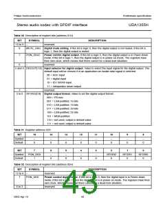
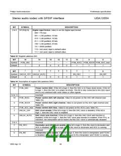
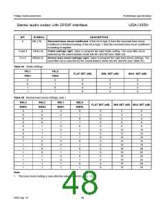
2 to 0 SFORI[2:0]
Digital input format. Value to set the digital input format:
000 = I2S-bus
001 = LSB-justified; 16 bits
010 = LSB-justified; 18 bits
011 = LSB-justified; 20 bits
100 = LSB-justified; 24 bits
101 = MSB-justified
110 = not used; input is default value
111 = not used; input is default value
Table 33 Register address 04H
BIT
15
14
13
12
11
10
9
8
Symbol
Default
PON_DAC
1
−
−
−
−
PON_ADCL PON_ADCR PON_ADC_bias
0
0
0
0
1
1
1
7
6
5
4
3
2
1
BIT
0
Symbol DACLK_OFF DACLK_AUTO
Default
−
−
−
EN_DEC
1
−
EN_INT
1
0
0
0
0
0
0
Table 34 Description of register bits (address 04H)
BIT
SYMBOL
PON_DAC
DESCRIPTION
15
Power control DAC. If this bit is logic 0, then the DAC is in Power-down mode; if this bit
is logic 1, then the DAC is in power-on mode. This bit is only connected to the DAC input
and is not combined with mute status or other signals.
14 to 11 −
reserved
10
PON_ADCL
Power control ADC left channel. Value to set power on the ADC left channel (see
Table 35).
9
PON_ADCR
Power control ADC right channel. Value to set power on the ADC right channel (see
Table 35).
8
7
PON_ADC_bias Power control ADC bias. Value to set power on the ADCs (see Table 35).
DACLK_OFF
DAC clock enable. If this bit is logic 0, then the DAC clock is disabled; if this bit is
logic 1, then the DAC clock is enabled.
6
DACLK_AUTO
DAC clock auto function. If this bit is logic 0, then the DAC clock auto function is
disabled; if this bit is logic 1, then the DAC clock auto function is enabled. If the FPLL is
unlocked, the interpolator will be muted and the DAC clock is automatically disabled.
5 to 3
2
−
reserved
EN_DEC
Decimator and ADC clock enable. If this bit is logic 0, then the clock to decimator and
ADC is disabled; if this bit is logic 1, then the clock to decimator and ADC is running.
1
0
−
reserved
EN_INT
Interpolator clock enable. If this bit is logic 0, then the clock to interpolator and FSDAC
is disabled; if this bit is logic 1, then the clock to the interpolator and FSDAC is running.
2003 Apr 10
44

 NXP [ NXP ]