Philips Semiconductors
Preliminary specification
Stereo audio codec with SPDIF interface
UDA1355H
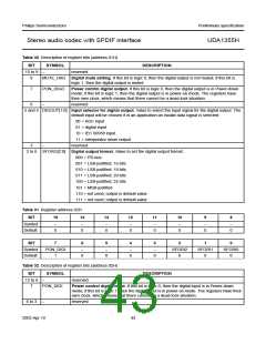
Table 30 Description of register bits (address 01H)
BIT
SYMBOL
DESCRIPTION
15 to 9
8
−
reserved
MUTE_DAO Digital mute setting. If this bit is logic 0, then the digital output is not muted; if this bit is
logic 1, then the digital output is muted.
7
PON_DIGO
Power control digital output. If this bit is logic 0, then the digital output is in Power-down
mode; if this bit is logic 1, then the digital output is in power-on mode. The registers have
their own clock, which means that there cannot be a dead-lock situation.
6
−
reserved
5 and 4 DIGOUT[1:0] Input selector for digital output. Value to select the input signal for the digital output. The
default input will be chosen if in an application an invalid data signal is selected:
00 = ADC input
01 = digital input
10 = IEC 60958 input
11 = interpolator mixer output
3
−
reserved
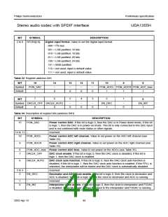
2 to 0 SFORO[2:0] Digital output format. Value to set the digital output format:
000 = I2S-bus
001 = LSB-justified; 16 bits
010 = LSB-justified; 18 bits
011 = LSB-justified; 20 bits
100 = LSB-justified; 24 bits
101 = MSB-justified
110 = not used; output is default value
111 = not used; output is default value
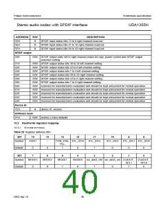
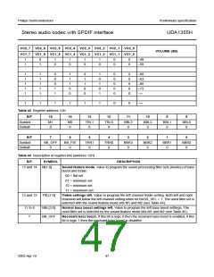
Table 31 Register address 02H
BIT
15
14
13
12
11
10
9
8
Symbol
Default
−
−
−
−
−
−
−
−
0
0
0
0
0
0
0
0
BIT
7
6
5
4
3
2
1
0
Symbol
Default
PON_DIGI
1
−
−
−
−
SFORI2
0
SFORI1
0
SFORI0
0
0
0
0
0
Table 32 Description of register bits (address 02H)
BIT
SYMBOL
DESCRIPTION
15 to 8
7
−
reserved
PON_DIGI
Power control digital input. If this bit is logic 0, then the digital input is in Power-down
mode; if this bit is logic 1, then the digital input is in power-on mode. The registers have their
own clock, which means that there cannot be a dead-lock situation.
6 to 3
−
reserved
2003 Apr 10
43

 NXP [ NXP ]