Philips Semiconductors
Preliminary specification
Stereo audio codec with SPDIF interface
UDA1355H
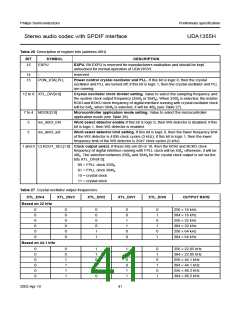
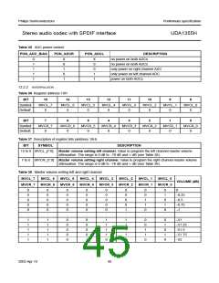
Table 26 Description of register bits (address 00H)
BIT
SYMBOL
EXPU
DESCRIPTION
15
EXPU. Bit EXPU is reserved for manufacturers evaluation and should be kept
untouched for normal operation of UDA1355H.
14
13
−
reserved
PON_XTALPLL
Power control crystal oscillator and PLL. If this bit is logic 0, then the crystal
oscillator and PLL are turned off; if this bit is logic 1, then the crystal oscillator and PLL
are running.
12 to 8 XTL_DIV[4:0]
Crystal oscillator clock divider setting. Value to select the sampling frequency and
the system clock output frequency (256fs or 384fs). When 256fs is selected, the master
BCKI and BCKO clock frequency of digital interface running with crystal oscillator clock
will be 64fs; when 384fs is selected, it will be 48fs (see Table 27).
7 to 4 MODE[3:0]
Microcontroller application mode setting. Value to select the microcontroller
application mode (see Table 28).
3
2
ws_detct_EN
ws_detct_set
Word select detector enable.If this bit is logic 0, then WS detector is disabled; if this
bit is logic 1, then WS detector is enabled.
Word select detector limit setting. If this bit is logic 0, then the lower frequency limit
of the WS detector is 4095 clock cycles (3 kHz); if this bit is logic 1, then the lower
frequency limit of the WS detector is 2047 clock cycles (6 kHz).
1 and 0 CLKOUT_SEL[1:0] Clock output select. If these bits are 00 or 10, then the BCKI and BCKO clock
frequency of digital interface running with FPLL clock will be 64fs; otherwise, it will be
48fs. The selection between 256fs and 384fs for the crystal clock output is set via the
bits XTL_DIV[4:0]:
00 = FPLL clock 256fs
01 = FPLL clock 384fs
10 = crystal clock
11 = crystal clock
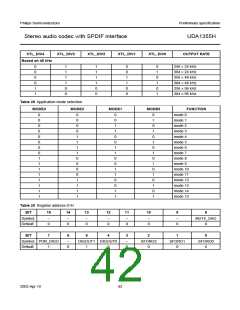
Table 27 Crystal oscillator output frequencies
XTL_DIV4
XTL_DIV3
XTL_DIV2
XTL_DIV1
XTL_DIV0
OUTPUT RATE
Based on 32 kHz
0
0
0
0
0
0
0
0
0
0
0
0
0
0
0
0
1
1
0
0
1
1
0
0
0
1
0
1
0
1
256 × 16 kHz
384 × 16 kHz
256 × 32 kHz
384 × 32 kHz
256 × 64 kHz
384 × 64 kHz
Based on 44.1 kHz
0
0
0
0
0
0
0
0
1
1
1
1
1
1
0
0
0
0
1
1
0
0
1
1
0
1
0
1
0
1
256 × 22.05 kHz
384 × 22.05 kHz
256 × 44.1 kHz
384 × 44.1 kHz
256 × 88.2 kHz
384 × 88.2 kHz
2003 Apr 10
41

 NXP [ NXP ]