This text is here in white to force landscape pages to be rotated correctly when browsing through the pdf in the Acrobat reader.This text is here in
_white to force landscape pages to be rotated correctly when browsing through the pdf in the Acrobat reader.This text is here inThis text is here in
white to force landscape pages to be rotated correctly when browsing through the pdf in the Acrobat reader. white to force landscape pages to be ...
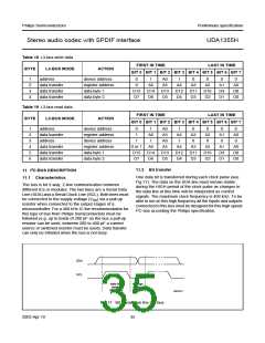
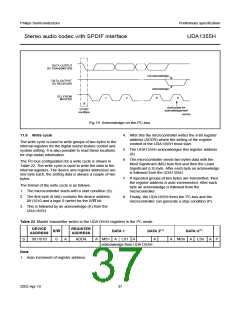
11.10 Read cycle
The read cycle is used to read the data values from the internal registers. The I2C-bus configuration for a read cycle is shown in Table 23
The format of the read cycle is as follows:
1. The microcontroller starts with a start condition (S).
2. The first byte (8 bits) contains the device address 0011010 and a logic 0 (write) for the R/W bit.
3. This is followed by an acknowledge (A) from the UDA1355H.
4. After this microcontroller writes the 8-bit register address (ADDR) where the reading of the register content of the UDA1355H must start.
5. The UDA1355H acknowledges this register address (A).
6. Then the microcontroller generates a repeated start (Sr).
7. Then the microcontroller generates the device address 0011010 again, but this time followed by a logic 1 (read) of the R/W bit. An acknowledge
(A) follows from the UDA1355H.
8. The UDA1355H sends two bytes data with the Most Significant (MS) byte first and then the Least Significant (LS) byte. After each byte an
acknowledged follows from the microcontroller.
9. If repeated groups of two bytes are transmitted, then the register address is auto incremented. After each byte an acknowledge follows from the
microcontroller.
10. The microcontroller stops this cycle by generating a Negative Acknowledge (NA).
11. Finally, the UDA1355H frees the I2C-bus and the microcontroller can generate a stop condition (P).
Table 23 Master transmitter reads from the UDA1355H registers in the I2C-bus mode
DEVICE
ADDRESS
REGISTER
ADDRESS
DEVICE
ADDRESS
R/W
R/W
DATA 1
DATA 2(1)
DATA n(1)
LSn NA
S
0011010
0
A
ADDR
A
Sr
0011010
1
A
MS1 A LS1
A
...
A
...
A
MSn
A
P
acknowledge from UDA1355H
acknowledge from master
Note
1. Auto increment of register address.

 NXP [ NXP ]