Philips Semiconductors
Preliminary specification
Stereo audio codec with SPDIF interface
UDA1355H
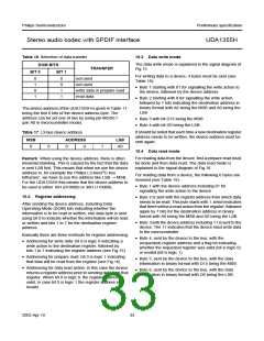
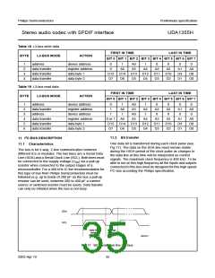
Table 18 L3-bus write data
FIRST IN TIME
LAST IN TIME
BYTE
L3-BUS MODE
address
ACTION
BIT 0 BIT 1 BIT 2 BIT 3 BIT 4 BIT 5 BIT 6 BIT 7
1
2
3
4
device address
register address
data byte 1
0
0
1
A0
A5
1
0
0
0
0
data transfer
data transfer
data transfer
A6
A4
A3
A2
A1
D9
D1
A0
D8
D0
D15
D7
D14
D6
D13
D5
D12
D4
D11
D3
D10
D2
data byte 2
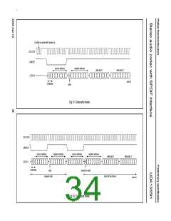
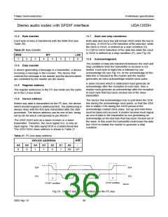
Table 19 L3-bus read data
FIRST IN TIME
LAST IN TIME
BYTE
L3-BUS MODE
address
ACTION
BIT 0 BIT 1 BIT 2 BIT 3 BIT 4 BIT 5 BIT 6 BIT 7
1
2
3
4
5
6
device address
register address
device address
register address
data byte 1
0
1
1
1
A6
1
A0
A5
1
A4
1
0
A3
0
0
A2
0
0
0
data transfer
address
A1
0
A0
0
A0
data transfer
data transfer
data transfer
0 or 1 A6
A5
A4
D12
D4
A3
D11
D3
A2
D10
D2
A1
D9
D1
A0
D8
D0
D15
D7
D14
D6
D13
D5
data byte 2
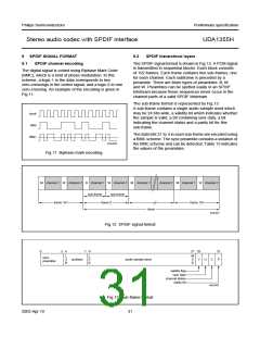
11 I2C-BUS DESCRIPTION
11.1 Characteristics
11.2 Bit transfer
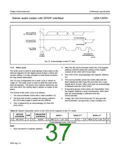
One data bit is transferred during each clock pulse (see
Fig.17). The data on the SDA line must remain stable
during the HIGH period of the clock pulse as changes in
the data line at this time will be interpreted as control
signals. The maximum clock frequency is 400 kHz. To be
able to run on this high frequency all the inputs and outputs
connected to this bus must be designed for this high speed
I2C-bus according the Philips specification.
The bus is for 2-way, 2-line communication between
different ICs or modules. The two lines are a Serial Data
Line (SDA) and a Serial Clock Line (SCL). Both lines must
be connected to the supply voltage (VDD) via a pull-up
resistor when connected to the output stages of a
microcontroller. For a 400 kHz IC the recommendation for
this type of bus from Philips Semiconductors must be
followed (e.g. up to loads of 200 pF on the bus a pull-up
resistor can be used, between 200 to 400 pF a current
source or switched resistor must be used). Data transfer
can only be initiated when the bus is not busy.
handbook, full pagewidth
SDA
SCL
data line
stable;
data valid
change
of data
allowed
MBC621
Fig.17 Bit transfer on the I2C-bus.
2003 Apr 10
35

 NXP [ NXP ]